LE5040 Quick Start Guide with LaserGRBL

Safety Guideline

Always exercise safety and caution when working with laser marking systems. Consider the listed recommendations to minimize risk:
- You must be at least 13 years old to operate the laser engraver.
- Direct exposure to the laser beam can cause severe burns and eye damage. Ensure that you are wearing proper laser safety goggles when working in the vicinity of the laser equipment.
- When you focus the laser do so only on the lowest power setting.
- Keep a fire extinguisher nearby since use of the laser may lead to an unexpected fire.
- Never leave an operating laser unattended.
- Fumes and smoke generated during the engraving/cutting process must be extracted from the room as some can be poisonous; make sure there is a ventilated system to the outdoors.
- Make sure the cutting area under the laser is metal or non-flammable.
- Ensure that the room or area you are operating the laser in is sufficiently labeled to prevent someone from unknowingly walking into an active work area.
- Be sure to disconnect the power when cleaning, maintaining or servicing the laser equipment.
- DO NOT stare at the bright and intense light appearing during the engraving process. Doing so can cause serious eye damage.
- Never use the laser except for the purpose intended.
SainSmart does not accept any responsibility or liability for any use or misuse of the Laser.
Setting Up LaserGBRL (Windows Only)
LaserGBRL is a free, laser specific controller for your CNC. It is capable of loading GCode, image files, both pictures and vector graphics and generating GCode optimised for laser engraving and cutting from them. You can find a quick overview of the LaserGRBL main window, as well as tutorials and details available on the website. Look here for more details.
Step 1: Downloading & Installing
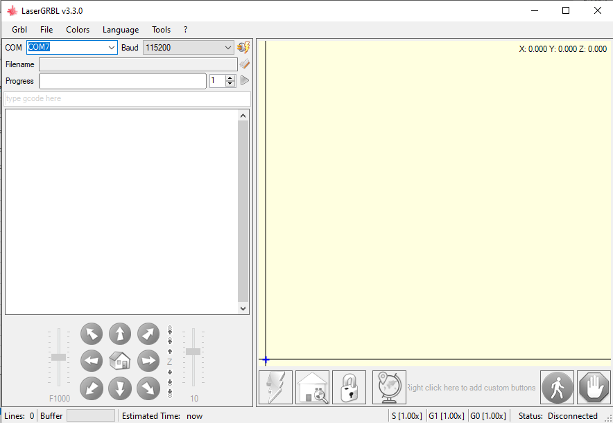
For setup, find the downloaded .exe file and double click/run it to install the software. After installation you can find a shortcut to start LaserGBRL. The window that launches should look like this:
Step 2: Driver Installation:
You now have a program to operate your laser engraver from, but there is an extra step needed to help this program communicate with the engrave.
This program is called a Windows Serial port driver, labeled CH340. To install, all you have to do is go into the Tools tab of LaserGRBL and select Install CH340 Driver. Windows security will flash asking for permission and after you give permission the following window will be shown to you:
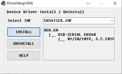
Select install and the process will complete itself.
Alternative Method:
If you cannot find this file, you can download it again from this link. Please not that the file linked is stored in a compressed .zip file. To use, you must extract the full contents of the .zip to a designated folder, and then try running the file from there. Running files from the .zip directly will not work.
Step 3: Installing Custom Buttons for Ease of Use
LaserGRBL allows you to add custom buttons to the bottom button bar, after the lightning bolt, padlock and globe. What these do is send GCode or setup commands to the router. Read here for background.
To add more functionality, you can download from here a file called “LE5040CustomButtons.gz” which you can import directly into LaserGRBL by right clicking in the custom button area, select Import custom Buttons and select the LE5040CustomButtons.gz file. You will have to confirm each button so just click yes to all the pop-up windows. The buttons add the following functionality:
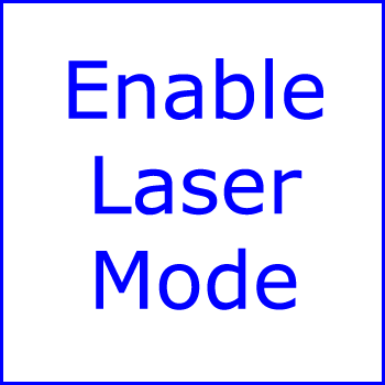
Enable Laser Mode
This button is something that you shouldn't need, but is good to have to be safe. All this does is tell your Laser Engraver to set $32 equal to 1. This makes sure that your controller firmware is set to Laser Mode, but it should be set as such by default.

Test Fire Laser
This button is useful for test firing and focusing your laser on your project material. By default it is set to 1/2 of a percent in order to make the laser just barely visible, but you can set it to whatever value you want by right clicking the button and select "Edit Button." To do so, change the S50 value to S[0-1000]. So, for example, if you wanted to test fire at 3% power, you would replace S50 with S300 and save the change; this can be altered as often as you wish, but lower is better to avoid burning your project materials.
Press the button again in order to deactivate the laser.

Frame Project
This is a very, very useful feature that will trace the outer rectangular perimeter of your project while the laser is firing at .5%. This is great for making sure that your project will fit on your stock material as well as letting you position your engraving with more care on a larger piece of stock material.

Tune Your Laser
This button is meant to optimize your Laser Engraver to get the most out of it as well as a few quality of life changes. In order to do so, it does the following:
- Increases Acceleration settings from 500 to 2000. Because the LE5040 is belt driven, it is capable of drastically higher acceleration values. This not only speeds up your project, but also helps keep edges from being burned for a cleaner look.
- Re-defines laser engraver work area from 200 x 200 to 500 x 400 to match listed specifications.
- Sets Maximum spindle value to 1000. The laser works on percentages on the users end, so this is to help ensure that all users of this guide have a consistent experience.
Should you want to, you can return the acceleration settings back to 500 by pressing this button again.
Connecting LaserGRBL to the LE5040
Step 1: Inspecting your Laser Driver (Make sure your engraver is not powered)
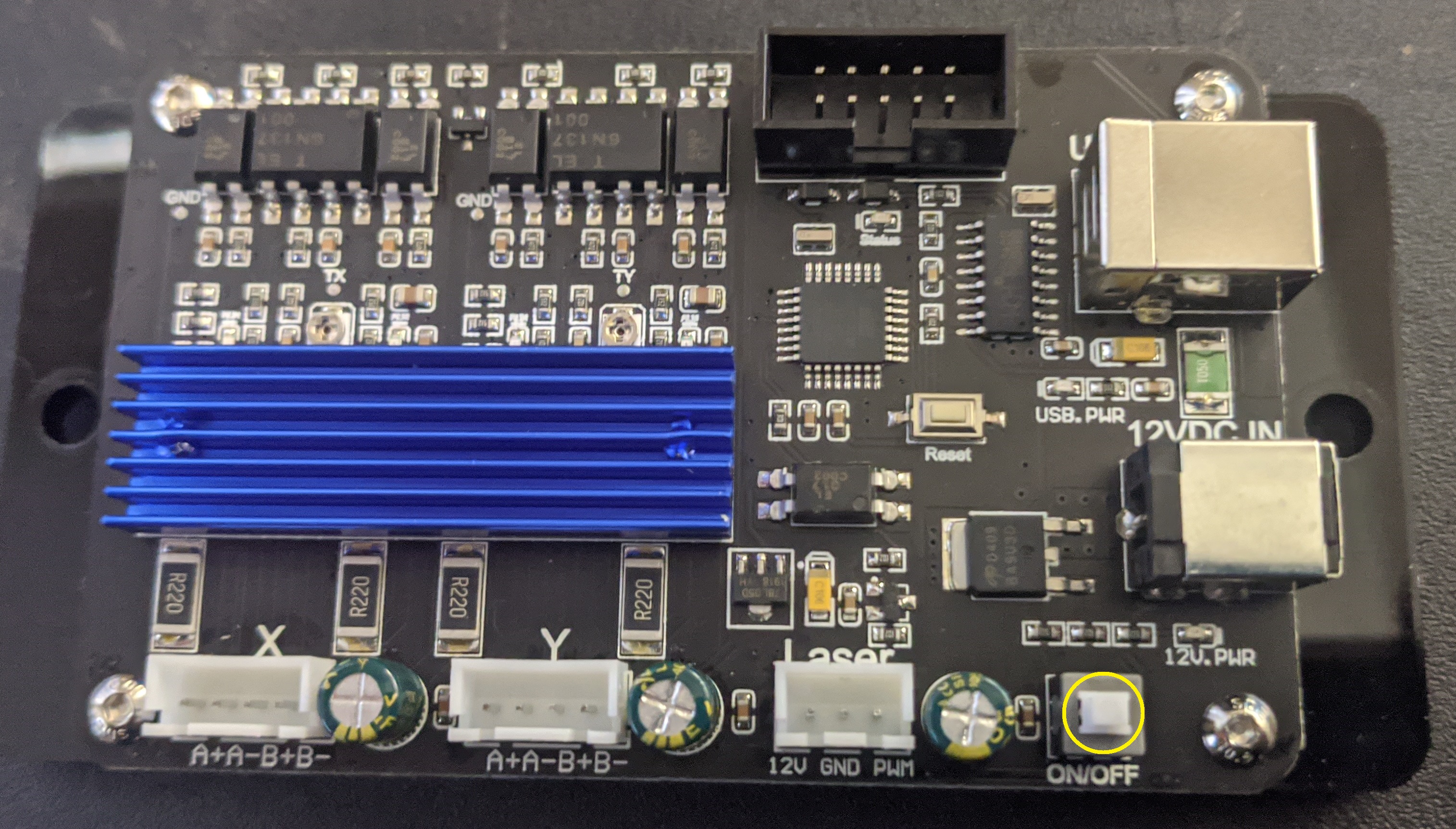
Between your laser and your controller board is another board called a Laser Driver which should look something like this:
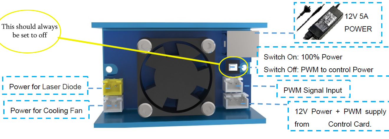
The white switch, while it may look like an On/Off switch is actually not what it seems. What this does is turn PWM mode on and off. PWM is the method by which the main board controls the laser, commanding it to turn on and off, as well at fire at different strengths. As a result PWM mode should always be enabled. If PWM Mode is disabled the Laser will fire at full power constantly the moment you turn your Laser Engraver on and you will have no control over it.
Step 2: Plug In & Turn on your LE5040
With your main control board connected both to the wall outlet through your power supply, as well as your USB cable to your computer, find the white switch shown below in the bottom right and turn your engraver on.
After you have done so, inspect the cooling fan on your Laser Module & Laser Driver, at this time they should both be running. If this is not the case, turn off your laser engraver and inspect the wiring to make sure it matches the user manual.
Step 3: Finding and connecting to your laser engraver in LaserGRBL
With your laser engraver powered up and connected to your PC via USB, focus your attention back to on LaserGRBL, and more specifically this part of the program:
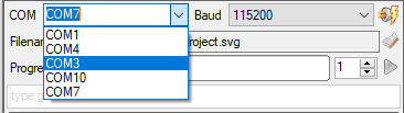
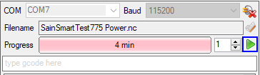
To connect to your laser engraver, you need to find the Com Port Address as well as the correct Baud Rate.
- Com Port: It's best to think of the com ports on your computer as the addresses of every device that is connected to your computer Via USB. These never change unless you change the USB port on your PC that you are plugged into, to another one.
In order to find the correct com port that represents your laser engraver, you can either use brute force by testing every port, or for an easier time, look at the drop down list, take note of all the numbers and then disconnect your laser engraver from your computer. Take a look at the list again, what com port disappeared? That's your laser engraver. - Baud Rate: Thing of this as the language that the program needs to speak in order to communicate with your laser engraver. In the case of the LE5040 it should always be set to 115200.
Once you have the correct Baud Rate and Com Port selected, press this button to attempt to make the connection:

If the connection was sucessful you should see the status in the bottom right corner change from "Status: Disconnected" to "Status: Idle." If this is not the case, your engraver may be off, or you might have the wrong Com Port selected.
Focusing The Laser
Now we are getting to the fun part! Find your stock material, for best results with this guide light colored woods like Maple, Cedar or Ash are best, but MDF works too.
With the material under the laser, press the Test Fire Laser button, you may need to double click it. You will use the knurled adjustment knob at the bottom of the Laser Module to bring the laser into focus. It is attached to the Laser Module through a threaded shaft which contains the focusing lenses.
The shaft is prevented from (easily) slipping by a spring mounted inside the laser which keeps some pressure on the shaft threads. By rotating the knob in different directions, you can bring the laser in and out of focus relative to a given surface, and keep in mind that you will need to re-focus the laser for each and every project.
As seen below, you essentially want to make the laser point on your project as small as is possible in order to find the Focus Point. While in the image below the focus point is round, do not be alarmed if it shows up as a very small line, just focus on making it as small as possible and things should be fine.
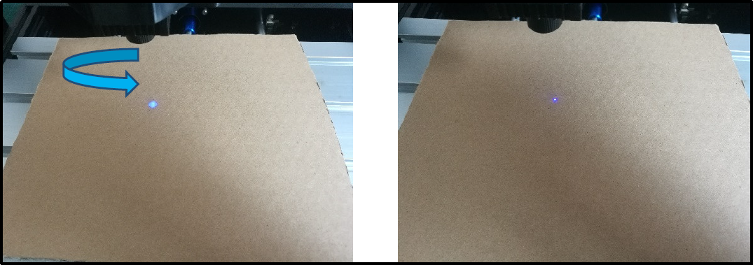
Focus Point
To cut or engrave efficiently we want the laser beam to be tightly focused into the smallest possible point at the top of the stock material. This depends on the distance from the laser emitter to the spot and is controlled by the position of the focusing lens as adjusted by the focusing knob.
The focal length is the distance from the lens to the point where the beam of light becomes a very fine dot and then expands again.
Loading Your Project
If you have your own files, now is the time to load it, but for the purposes of this quick-start guide we are going to be using a pre-prepared test file which you can download here. Alternatively, for those who want to experiment, you can find the source SVG here.
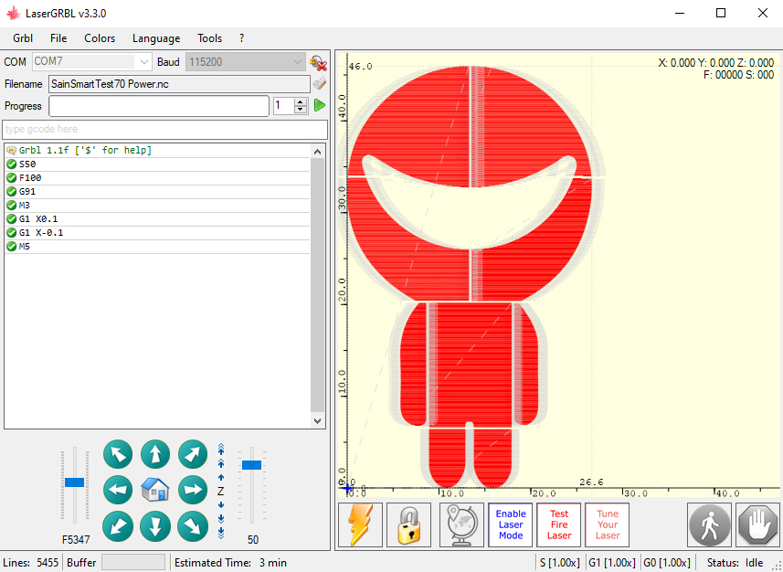
Open SainSmartTest70 Power.nc SainSmartTest70 Power.nc in LaserGRBL and your program should show this:
Final Setup & Running Project
Take note of the location of the cross-hair in the bottom left corner of the visualizer:
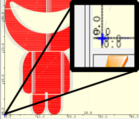
This represents your start point/origin for your project. The way that LaserGRBL works is that wherever your laser is when you load you file, that becomes the start point/origin. In this case, the laser will engrave within an approximately 30 mm wide by 50 mm tall rectangle, with the bottom left corner of the rectangle being that start point/origin.
But what if you need to re-position the laser? To do so, jog as needed using the arrow controls to position the engraving where you would like and then press this globe button, which resets the origin/start point to your current position:

Next, it is good practice to use the Frame Project button in order to better visualize where the project will be engraved, as well as let you make sure that everything will fit on your stock material.
Finally, don't forget to press the Tune Your Laser Button this one and only time; the settings will be saved permanently.
Does the frame look good to you? Is you're laser focused? If so, you're good to go! Go ahead and put on your protective eye wear and press the triangular play button to run your project
Analysis of Engravings & Material Testing
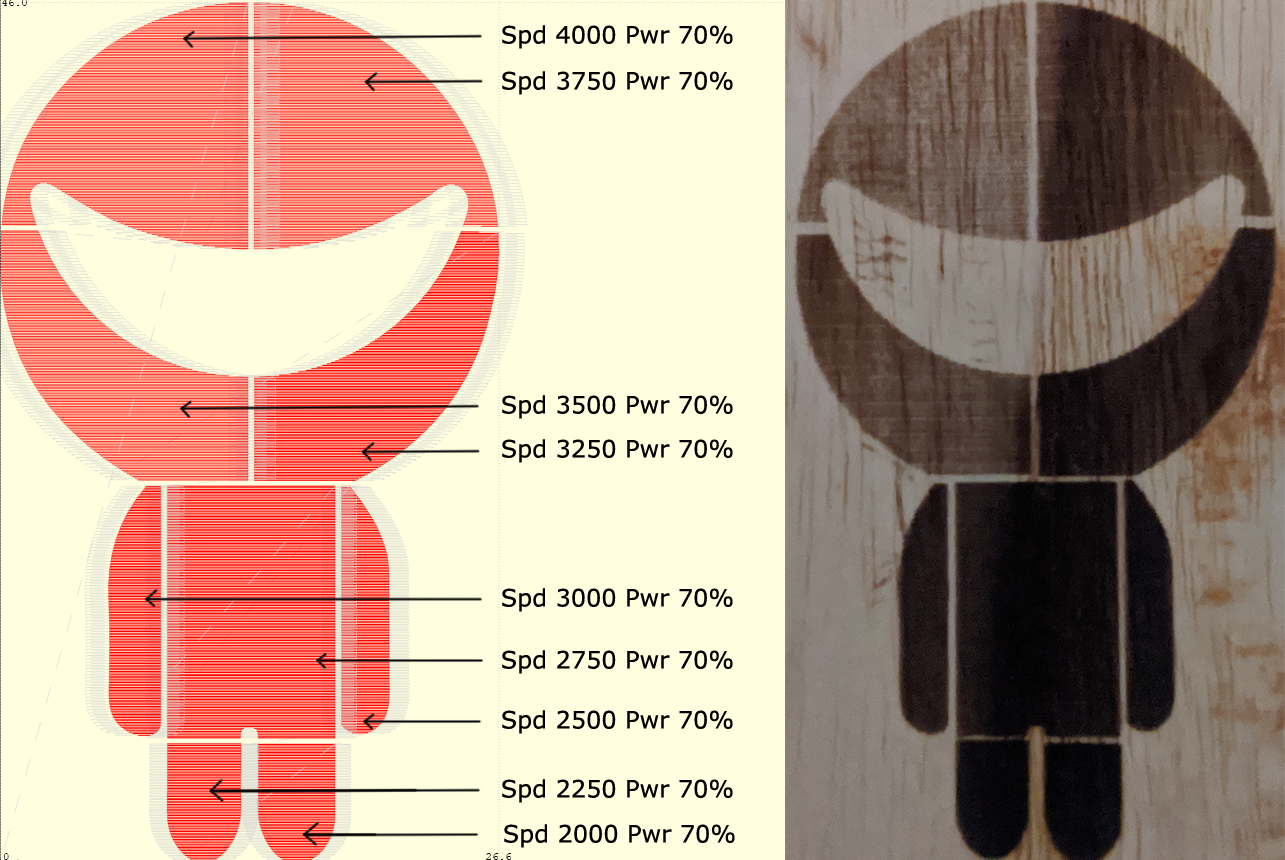
You may have noticed if you kept a well protected eye on the project as it was being engraved that each of the 10 pieces that make up the SainSmart mascot was engraved slightly faster than the last.
This is entirely intentional to teach you one final lesson about the process of laser engraving: Testing!
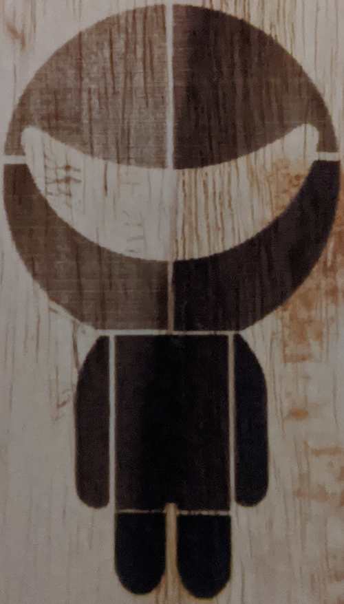
The real world is messy, so even the laser engraving masters will need to test laser engraver settings against their materials. Some settings will be "Bad" leading to undesirable results, but even with "Good" settings there is a gradient of effects to pick from. The results of your engraving might vary from the one shown above (ash wood was used) but lets dissect the engraving to get an understanding of what we can learn using a file like this.
- The Legs: At speeds of 2000 to 2250 respectively, these would fall into the category of Bad: Too Slow. We can see this because while they are a nice solid black color, the legs are slightly larger than they should be compared to the simulation to the right (See how thin the lines are between the legs and the torso?)
- The Arms, Torso & Bottom - Right Head Quarter: Ranging in speed between 2500 and 3250 what we are seeing here is a spectrum of "Good" settings which all show clean edges and and consistent coloration where a user can pick to have solid black engravings or decide to leave a bit of the wood grain showing.
- Note that while the arms and torso look the same, if you had this engraving in hand you would see that each engraving right to left is shallower than the last. Depending on your needs any of the three could be desirable.
- The Rest of the Head: At speeds of 3500 to 4000 respectively, these would fall into the category of Bad: Too Fast. While at first glance these might seem nice for a light engraving which leaves the wood grain well exposed, go ahead and take a closer look; see all those countless little lines? Those are undesirable scan line artifacts which are undesirable. When you see this, it means that you either need to increase the power, or reduce the speed.
Modifying the Test File for Your Needs
The engraving shown above is the best result to show you how this testing process should work among many attempts. Often times everything would be very deep & charcoal black, while other times everything was so light that the laser did not even burn parts.
Testing is a process of dialing in your settings to get a desired result. If the whole thing engraved like the legs above there would be need to try again with lower power settings or faster speed (It's best to only change one variable at a time). Since faster is better lowering the power is usually more ideal. If you need to do this, here is how.
NC files can be opened in any text editor, Microsoft Notepad was used here:
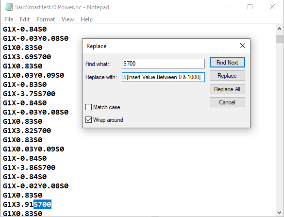
The Power setting is constant throughout the file as S700 (which is 70%). As a result, if you select Edit > Replace the toolbox above shows up. by typing S700 in the "Find what:" category and, lets say, S850 in the "Replace with:" category, you can then click Replace All and every instance of the old power setting will be replaced with the new one. Once you have done so just save your file and open it in LaserGRBL and you're good to go for a lower/higher power test.