Coreception 3D Printer Trouble Shooting
 Updated
Based off of the works of by Dustin Speed
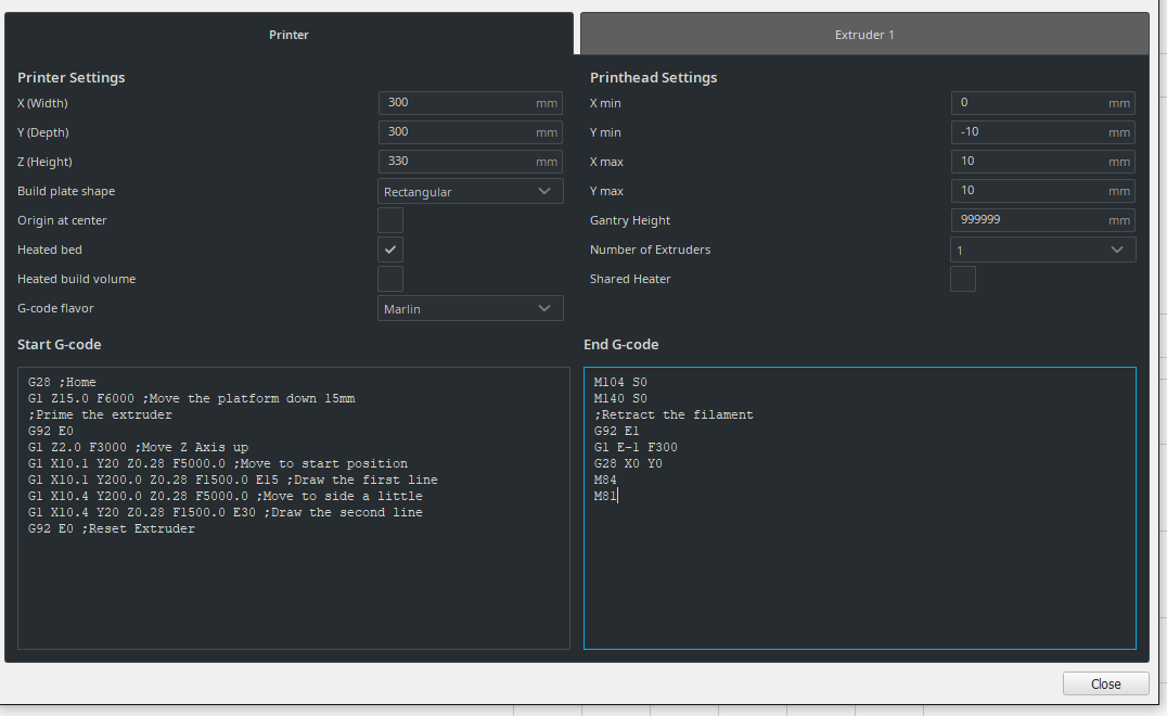
1. Cura settings (specifically print head size settings and why they are)
There is a known bug for the x-min and the y-min. These settings are used to set the hot end size for the options to print all at once or island. This is not a concern with the coreception as the print dimensions takes into account the size of the print head.
·For versions that do not allow the recommended settings use the below:
·x min = 0
·y min = -10
·x max = 10
·y max =10
2. Can I add BLtouch? And what hardware works?
There are multiple versions and we have not tested or configured all of them. This is only recommended if you have prior knowledge or experience with 3d printing hardware. There is a configuration guide that is provided to give general knowledge.
3. BLtouch not working, never extends.
In general control issues are related to the 2 pin white and black cable/connection. The self will work as long as the 3 pin connector is in place and working.
·The white and black 2 pin cable is connected to z-min/max white (to s) black (to ground).
·In the guide provided the z min is used. Ensure that the correct z connector is the one you have configured.
Configure BLtouch connector via configuration file robin_nano35_cfg.txt. The below tells it which plugs are in use on your motherboard. Ensure z min/max depending on the one you use is enabled. (Should have a 1 next to the one you choose to use)
# Specify here all the endstop connectors that are connected to any endstop or probe.
>USE_XMIN_PLUG 1 # 1:used; 0:noused
>USE_YMIN_PLUG 0 # 1:used; 0:noused
>USE_ZMIN_PLUG 1 # 1:used; 0:noused
>USE_XMAX_PLUG 0 # 1:used; 0:noused
>USE_YMAX_PLUG 1 # 1:used; 0:noused
>USE_ZMAX_PLUG 1 # 1:used; 0:noused
In the configuration file robin_nano35_cfg.txt. Tells the bltouch if it should function as a min end stop or a max endstop.
BLTOUCH 1 # 0:disable BLTOUCH; 1:enable BLTOUCH
#Select for a probe connected to Z-Min or Z-Max.
>Z_MIN_PROBE_PIN_MODE 2 # 0 : NULL; 1: ZMIN; 2: ZMAX
4. What firmware can I use?
Official firmware is available.
There is a newer version of offical firmware available here.
Unofficial firmware (Please use with caution as these are not tested and may cause unintended behavior and possibly void your warranty)
MKS provides multiple flavors of firmware for the MKS robin nano 1.2 board that is used in the Coreception 300 printer.
Oldest version of marlin 2.0 based firmware. Most similar to 2.3/2.4 stock firmware. Click here to download.
Most current stable version of the MKS based on Marlin 2.0. Click here to download.
Marlin 2.0 new fork to add a colorful GUI. Click here to download.
5. How do I perform the firmware upgrade?
There is a newer version of offical firmware available here.
·Extract the contents of the firmware to a micro SD card.
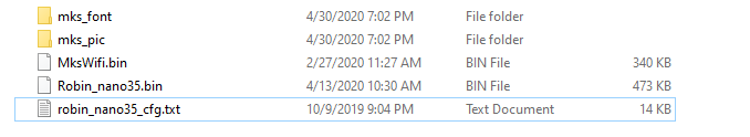
·Optional you can set configuration items via the robin_nano35_cfg.txt file. This file is required even if you do not perform any customization.
·Place the sd card in the printer ensure that it is powered off.
·Start the printer and the firmware upgrade will begin.
Common issues with firmware upgrades
·If the firmware completes but you do not see proper icons after it completes. Please try again or try a different SD card. Seems to be predominately on slower SD cards
·If you complete the upgrade process and it powers on but then powers off again. Repeat the firmware again. Check to ensure the configuration file is present on the card.
6. Temp on bed or extruder shows negative or extreme numbers.
·Most common issue is that the connection is loose or disconnected.
·Extruder should be in the black e0 thermistor connector. This is very close to the wall on the board when it is installed in the coreception 300.
·Hotbed should be in the white connector on the right edge also very close to the edge when installed in the coreception 300.
·The extruder thermistor is connected to the VGA breakout on the gantry (where the VGA cable connects behind the extruder). Check the connection there to ensure it is firmly plugged in and there are no broken or bare wires.
·If all connections are in place and not broken wires are observed it may be a component failure.
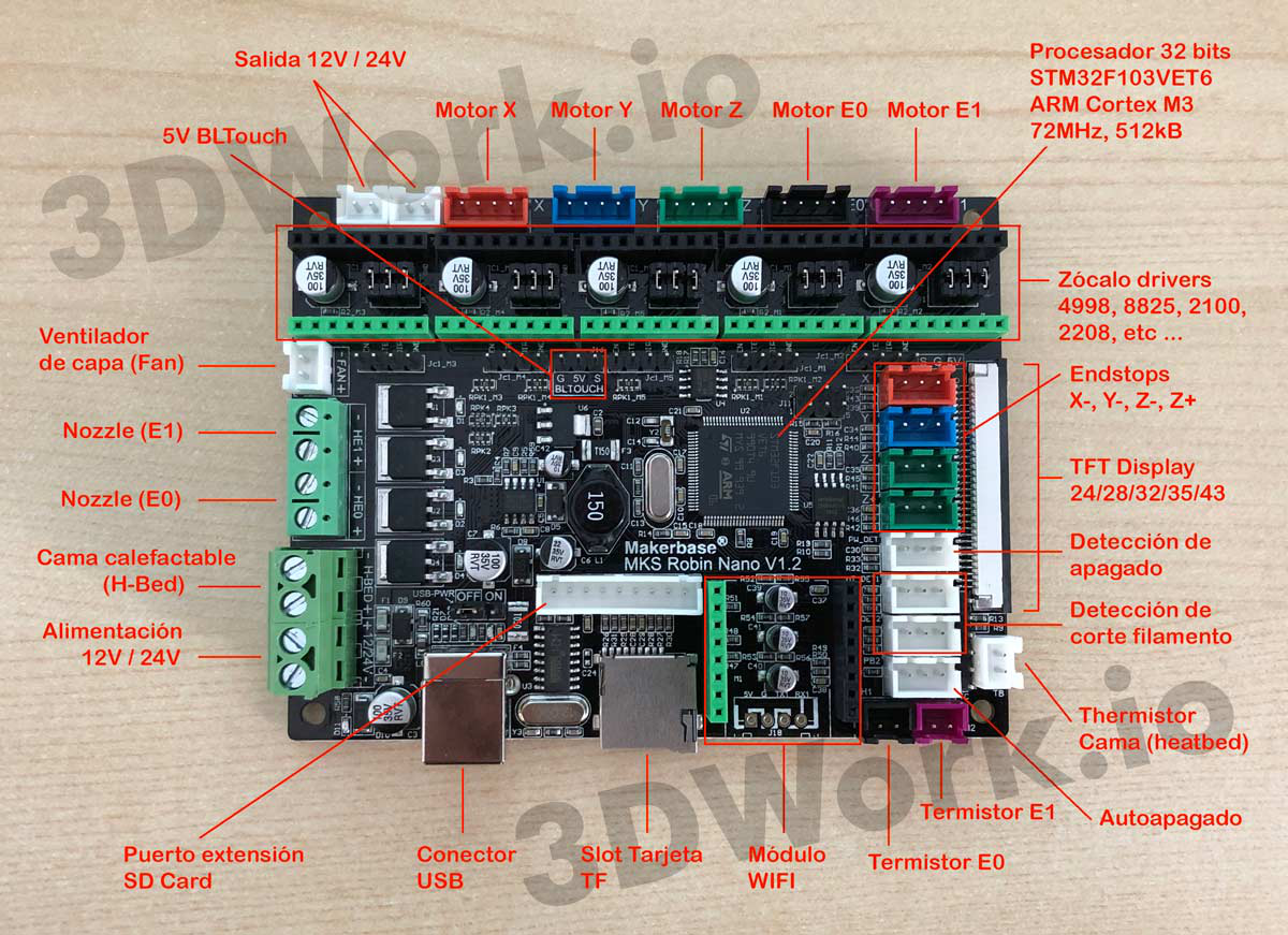
Image via 3dwork.io

7. Print stops halfway and reports as complete.
·The most common cause is that there was a filament jam/runout. Or clogged nozzle.
·Check for tangled filament on the spool.
·Check and make sure the filament is seated properly in the extruder.
·Heat the nozzle and ensure the filament is flowing as expected using the load filament menu.
8. What is the motor amps for all 5?
1.0 A for X, Y, Z, E1 motors; 0.8A for E0 motor.
9. Can the extruder be mounted remote/long/Bowden configuration?
·There are many configurations to do this. The easiest is to remove the extruder assembly from the top of the hot end gantry assembly. This is a simple process of removing the 2 screws to left side near the motor connector.
·Once that has been accomplished you can use t-slot screws to mount the entire assembly in any location around the perimeter of the printer.
·Lastly you will need a cable to connect the extruder motor. The coreception default configuration has the motor cable coming off the VGA breakout box. You will need a cable that will reach from the board under the machine. To the selected location of the remote extruder. The new cable should connect to the Motor e0 pictured below.
·Example T-slot nut assortment from amazon. Click here.
·Example motor cable from amazon. Ensure your motor connectors are the same. Click here.
Image via 3dwork.io

10. What are the stock stepper drivers?
·X and Y use MKS 2208 v1.0 in standalone mode.
·E uses a MKS A4988
·Both Z drives use MKS A4988
11. What is the leadscrew pitch?
It is 2mm pitch with a 4starts (effective pitch of 8 mm)
12. What Degree is the z axis steppers?
1.8 degrees.
13. What mode micro stepping are stepper driver using?
1/16 stepping.
14. Jerking or no movement on 1 or more axis or Z lead screws.
·This is typically a failure of the stepper driver or a disconnected motor cable.
·Check the cabling on the board for the affected direction. If all cables are connected. Please reach out to support.
Image via 3dwork.io
15. SD card will not click lock.
Could be a damaged Port. Please contact Tech Support via support@sainsmart.com.
16. Homing leveling Issues. Bed crashes into head or pushes lead plate out of plane.
·If you have issues with this check the z-stops. They have a tendency to crack across the mounting screws.
·Replacement brackets can be printed.
Download the original version.
Download the upgraded version.
17. No power on or flicker and stop when starting the printer.
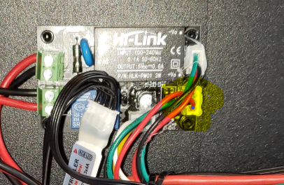
There is a possibility the HI link power loss module could be the cause of the issue. You can test this by disconnecting the cable highlighted in yellow below. In any case, please reach out to SainSmart support via support@sainsmart.com.
18. Is UART mode supported?
Currently the robin nano 1.2 does not support UART. But UART drives can be used in standalone mode.
19. How do I tune e-steps for my extruder stock or after market?
Not recommended for beginners.
If you tuner is either under or over extruding you may need to tune the e steps on the extruder.
You have to be able connect to the printer with octoprint, simplfy3d, or Pronterface. These are the ones I know and use many more will work.
Required materials. A ruler or caliper capable of measuring 120 mm. A piece of tape (I actually tear off the sticky part of a sticky note works great for this) or marker capable of marking on filament.
Issue command G503 Locate the M92 E##. Should be 381.5 on the coreception if you have never changed it.
Ensure you have filament loaded and heat the extruder to your common print temperature.
From the top of the extruder measure 120 MM and mark with tape/sticky note/marker.
Send: G1 E100 F100 This extrudes 100 mm of filament.
Once the move has completed measure from the extruder to the mark made. Let’s use 24mm as an example.
We should now have the information to calculate the proper E-steps.
Example below
Subtract your left over filament from 120. This will give us the actual amount of filament that was extruded.
120 – 24 = 96
Now take the steps and multiply by 100 to get the number of steps that were taken to extrude the 96 mm in our example.
381.5 X 100 = 38,150 steps
Now take the steps taken and divide by length extruded.
38150 / 96 = 397.4
Now let’s set our new value.
M92 E397.4 (sets the value)
M500 (saves the value)
M501 (Load from memory I do this with all changes to ensure they are in use)
M503 (only used to verify)
This is recommended to do anytime you change nozzles, hot end, extruder, stepper drivers or extruder motors. If you wish you can rerun the test with the new setting this will get you more and more accurate. On every pass. I have however never really had it not be great after the first pass.
20. Bang Bang vs PID (how to change between them.)
You can use either bang bang or PID for heating on the extruder and hotbed. By default the extruder uses PID and the hotbead uses Bang Bang. If you wish to change between modes you can change it from the screen if you are using any of the firmware that is based on marlin 2.0. If you are using an older version you will need to change it via the firmware config file (robin_nano35_cfg.txt). The sections you need to modify are below.
# Type of heat manager for extruder.
>PIDTEMPE 1 # 1:PID ; 0:bang-bang
>DEFAULT_Kp 22.2 # --default
>DEFAULT_Ki 1.08 # --default
>DEFAULT_Kd 114 # --default
#Type of heat manager for this heatedBed.
>PIDTEMPBED 0 # 1:PID ; 0:bang-bang
>DEFAULT_bedKp 10.00 # --default
>DEFAULT_bedKi 0.023 # --default
>DEFAULT_bedKd 305.4 # --default
21. PID tuning guide
You have to connect to the printer with octoprint or simplfy3d or Pronterface.
Issue the below g-code:
M303 E0 S215 C10
This will take a few minutes it will try to set the hotend to 215 and then cycle it 10 times.
You will see a few values popup. But wait till you see this one.
Clasic PID
Kp: 17.230
Ki: 1.660
Kd: 44.790
PID Autotune finished ! Place the Kp, Ki and Kd constants in the configuration.h
Now you know what they are we need to save them.
Sets the PID current:
M301 P17.230 I1.660 D44.790
Save the PID to eeprom so you can restart without it resetting:
M500
If you load a new firmware it will overwrite these. But there is a trick!!
Open your robin_nano35_cfg.txt with your firmware files. And look for the below. You can
set them via the below entries.
# Type of heat manager for extruder.
PIDTEMPE 1 # 1:PID ; 0:bang-bang
>DEFAULT_Kp 17.230 # --default
>DEFAULT_Ki 1.660 # --default
>DEFAULT_Kd 44.790 # --default
#Type of heat manager for this heatedBed.
>PIDTEMPBED 1 # 1:PID ; 0:bang-bang
>DEFAULT_bedKp 118.480 # --default
>DEFAULT_bedKi 22.610 # --default
>DEFAULT_bedKd 155.200 # --default
By default on the coreception heatbed is set for bang mode. If you want to change it I would run the same as you do for the extruder. Just set a lower temp (max of 100) and we have to specify the bed.
Run the bed autotune:
M303 E-1 S60 C8
Set the PID for the bed:
M304 P118.480 I22.610 D155.200
To save:
M500
To verify use M503.