Ender 3 V2 3D Printer Assembly
 Updated
- Part 1-Unboxing
- Part 2-Mechanical installation
- 2.1 Install Z-axis Limit Switch Assembly and Z-axis Profiles
- 2.2 Install Z-axis Motor Assembly and Lead Screw
- 2.3 Install Bowden Tube Connector, XE-axis Assembly and Drive Belt
- 2.4 Install Nozzle Assembly, Z-axis Roller Bracket Assembly
- 2.5 Install X-axis Tensioner and Connect the Drive belt.
- 2.6 Install the Z-axis Gantry Assembly and Adjust X-axis and Y-axis Drive belt Tension
- 2.7 Install the Gantry Profile and Display Assembly
- 2.8 Install Filament Holder, Gantry Cover and Extruder Knob
- 2.9 Connect the Bowden Tube to the Extruder
- 2.10 Electrical Connections
Part 1-Unboxing
Please make sure all the following parts are included. If you are missing any part or have any questions, please email us at support@sainsmart.com
- 1 x Printer Base
- 1 x Display Assembly
- 1 x Nozzle Assembly
- 1 x Z-axis Roller Bracket Assembly
- 1 x X-axis Tensioner
- 1 x Z-axis Motor Assembly
- 1 x Z-axis Limit Switch Assembly
- 1 x XE-axis Assembly
- 1 x Z-axis Profile (left)
- 1 x Z-axis Profile (right)
- 1 x Gantry Profile
- 1 x X-axis Profile
- 1 x Lead Screw
- 1 x Filament Holder Upright
- 1 x Filament Holder Pipe and Nut
- 2 x 2020 Profile Cover
- 1 x Drive Belt
- 1 x Metal Scraper
- 1 x Diagonal Cutters
- 1 x Cable Tie
- 1 x Needle
- 1 x SD Card and Card Reader
- 2 x Bowden Tube Connector
- 1 x Power Cable
- 1 x Wrenches and Screwdrivers
- 2 x Joint Claw
- 2 x Hexagon Socket Flat Round Head Screw M5x8
- 2 x Hexagon Socket Countersunk Head Screw M4x18
- 5 x Hexagon Socket Head Spring Washer Combination Screw M5x25
- 2 x M5 T Nut
- 5 x Hexagon Socket Head Spring Washer Combination Screw M5x45
- 5 x Hexagon Socket Flat Round Head Spring Washer Combination
- 1 x Filament
- 1 x Extruder Knob
- 1 x Hexagon Socket Countersunk Head Screw (black) M4x14
- 1 x Nozzle
Part 2-Mechanical installation
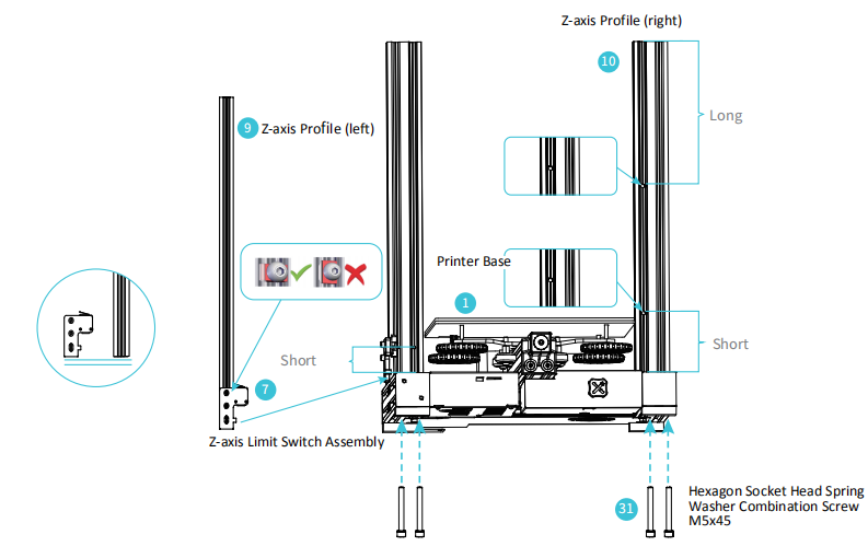
2.1 Install Z-axis Limit Switch Assembly and Z-axis Profiles
What you will need
- 1 x Printer Base
- 1 x Z-axis Limit Switch Assembly
- 1 x Z-axis Profile (left)
- 1 x Z-axis Profile (right)
- 5 x Hexagon Socket Head Spring Washer Combination Screw M5x45
Step 1: Slide the Z axis limit switch onto the Z-axis Profile (left) as in the picture above and loosely tighten. Then use four M5X45 screw to fix the Z-axis profiles to the base.
Step 2: Slide the Z axis limit switch down until it touches the base profile and tighten the bolts.
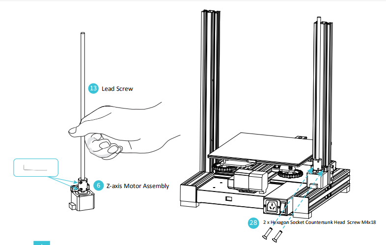
2.2 Install Z-axis Motor Assembly and Lead Screw
What you will need
- 1 x Lead Screw
- 1 x Z-axis Motor Assembly
- 2 x Hexagon Socket Countersunk Head Screw M4x18
Step 1: Attach the motor to the profile using two M4x18 screws it needs to be secure but do not over tighten.
Step 2: Slide the lead screw into the top of the coupler and tighten the grub screw to clamp it securely in place.
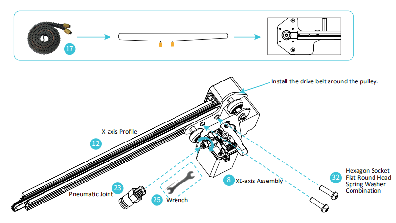
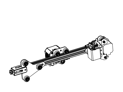
2.3 Install Bowden Tube Connector, XE-axis Assembly and Drive Belt
What you will need
- 1 x XE-axis Assembly
- 1 x X-axis Profile
- 2 x Bowden Tube Connector
- 2 x Hexagon Socket Flat Round Head Spring Washer Combination
- 1 x Drive Belt
- 1 x Wrenches and Screwdrivers
Step 1: Tighten the Pneumatic tube connector firmly into the Extruder using an open-end wrench.
Step 2: Align the bolt head on the XE-Axis Assembly into the hole on the X Axis profile.
Step 3: Secure the XE-axis Assembly to the X-Axis Profile with two M4X16 screws. (Insert the Allen key through the holes on the outer plate).
Step 4: Install the Drive belt round the pulley inside the XE-axis Assembly with the toothed side round the pulley as shown above.
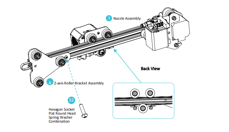
2.4 Install Nozzle Assembly, Z-axis Roller Bracket Assembly
What you will need
- 1 x Nozzle Assembly
- 1 x Z-axis Roller Bracket Assembly
- 1 x Hexagon Socket Flat Round Head Spring Washer Combination
Step 1: Make sure the drive belt is in the profile slot and slide the Nozzle assembly onto the profile as shown above.
Step 2: Attach the Z-Axis Roller Bracket Assembly to the profile, aligning the bolt head into the hole on the profile and using the M4x16 screw into the threaded hole in the profile.
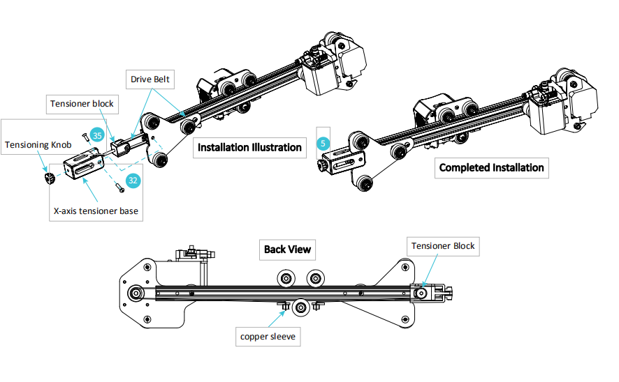
2.5 Install X-axis Tensioner and Connect the Drive belt.
What you will need
- 1 x X-axis Tensioner
- 1 x Hexagon Socket Flat Round Head Spring Washer Combination
- 1 x Hexagon Socket Countersunk Head Screw (black) M4x14
Step 1: Undo the tensioning knob and remove the tensioner block.
Step 2: Thread the drive belt around the pulley making sure it has not twisted and push the pulley back into the tensioner base making the alignment is as shown in the picture above.
Step 3: Screw the tensioning knob back into place by couple of turns.
Step 4: Attach the Tensioner base to the profile Z Axis Roller Bracket assembly with a M4X16 screw on one side and the countersunk screw (in the Tensioner block bag) on the other, both these screws use the same threaded hole in the profile.
Step 5: Secure the ends of the drive belt by sliding the belt into the slots in the Nozzle assembly as in the picture above.
2.6 Install the Z-axis Gantry Assembly and Adjust X-axis and Y-axis Drive belt Tension
What you will need
Assembled Part After Mechanical installation Section 2.5
Assembled Part After Mechanical installation Section 2.2
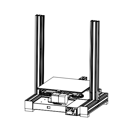
Step 1: Place the lower V rollers into the grooves on the outside of the Z profiles.
Step 2: Locate the lead screw in the Brass nut on the XE Assembly and turn by hand to screw the gantry down while guiding the other V rollers into the Z profile grooves.
Step 3: Adjust the tension of the X and Y axes drive belts as shown above.

Tips:
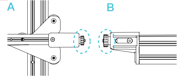
Turn the X-axis and Y-axis tensioner knobs to adjust the belt tension.The belts should be taught but not over-tight or too slack. When you press down the drive belt, you should feel some spring in the belt.
If the belts are too lose they can slip during printing ruining the result.
If the belts are too tight they will over stress the pulleys and motors or even break.
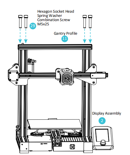
2.7 Install the Gantry Profile and Display Assembly
What you will need
- 1 x Gantry Profile
- 1 x Display Assembly
- 4 x Hexagon Socket Head Spring Washer Combination Screw M5x25
Step 1: Fix the Gantry profile onto the upper end of the gantry with four hexagon socket head cap screws M5x25 and tighten securely:
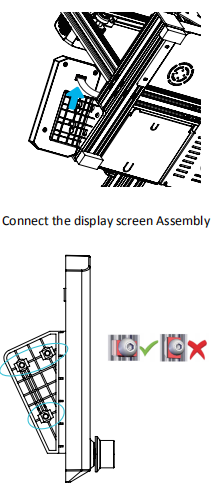
Step 2: Unclip the display from the bracket, slacken the screws pre-installed on the bracket and insert the T nuts into the base profile.
Step 3: Tighten the bolts making sure the T nuts are turning to engage with the base profile.
Step 4: The display can be moved forwards and backwards to suit your preference then tighten the bolts.
Step 5: Connect the ribbon cable to the display screen and clip it back onto the bracket.
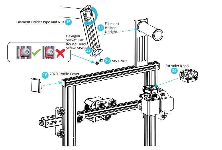
2.8 Install Filament Holder, Gantry Cover and Extruder Knob
What you will need
- 1 x Filament Holder Upright
- 1 x Filament Holder Pipe and Nut
- 2 x 2020 Profile Cover
- 2 x Hexagon Socket Flat Round Head Screw M5x8
- 2 x M5 T Nut
- 1 x Extruder Knob
Step 1: Insert the M5X8 bolts through the holes on the Filament holder upright and loosely attach the T nuts.
Step 2: Align the T Nuts in the top profile groove (The flat side faces towards the back of the printer) and tighten the nuts, the T nuts will turn in the grove as it tightens.
Step 3: Attach the filament holder and secure with the plastic nut.
Step 4: Place the extruder knob onto the top of the extruder motor shaft and push the profile covers in on both sides of the top profile.
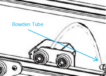
2.9 Connect the Bowden Tube to the Extruder
What you will need
- 2 x Joint Claw
Step 1: Press the collar on the extruder Pneumatic Connector in to the fitting and hold.
Step 2: Press the Bowden tube into the connector firmly until it goes no further.
Step 3: Release the collar.
Step 4: Clip the Connector spacer between the collar and the body of the connector to lock in place.
2.10 Electrical Connections
What you will need
- 1 x Power Cable
- 1 x X, E, Z-axis Motor Port
- 1 x X,Z-axis Limit Switch
Step 1: Connect the X, E, and Z-axis stepper motors according to the yellow labels on the 6pin (4 wire) connector. The keys on the plugs must be correctly aligned with the socket first.
Step 2: Connect the X and Z-axis limit switches according to the yellow label on the 3pin (2wire) connectors. The keys on the plugs must be correctly aligned with the socket first.
Step 3: Check the correct input voltage has been selected.
Step 4: Plug in the power cord (as shown) and toggle the power switch to turn the machine on.
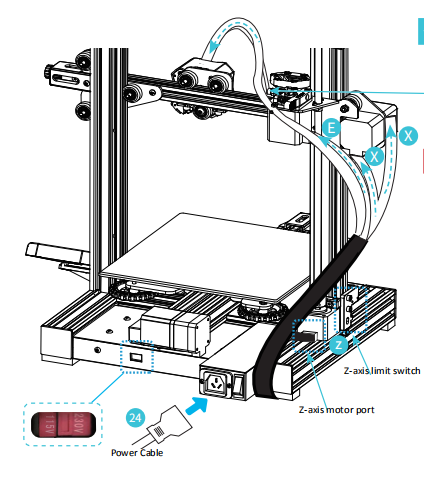
Caution:
- Select the correct input voltage to match your local supply (115/230V)
- Damage can occur if the voltage is set incorrectly.
- Connect the power cord and set the power switch to 1 to turn it on.
- Do not unplug or connect any cables when the machine is turned on.