How to Color Engraving in Stainless Steel (Test Grid Generation Guide)
 Updated
Test Grids Generation Guide
LightBurn offers an integrated feature for creating test patterns, which can be instrumental in determining the optimal settings for your specific laser and material pairing. This feature can be located within the LightBurn menus under Laser Tools > Material Test. In this guide, we will use stainless steel as a representative example.
*Note: the color effect can vary based on the material used, and significant changes can occur with alterations in power and speed. Therefore, it is advised to conduct material testing and refer to your post-testing parameters for optimal results.
Preparation Steps:
1. Ensure the machine, computer, and camera are properly connected.
2. Prepare the material you intend to test (e.g., stainless steel).
3. Adjust the focus in accordance with the engraving material.
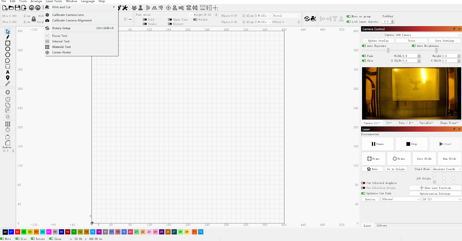
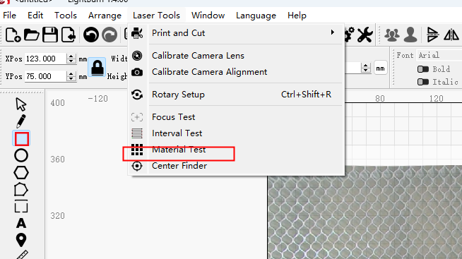
Step 1 Turn on the Material Test
Select and click “ Laser Tools”-> “ Material Test”
Step 2 Set the Test Scope
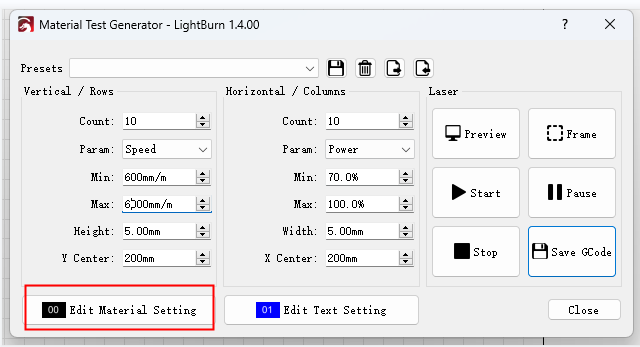
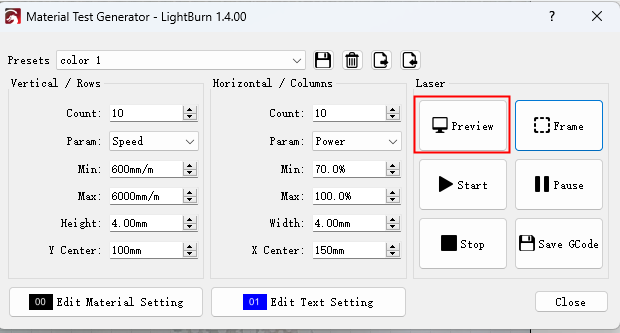
2.1 Fill in parameters
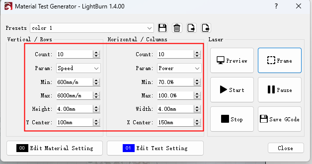
Parameter instructions:
Vertical / Rows refers to the Y-axis
“Count”: The number of grids
“Param”: Speed
“Height”: The grid’s height
Horizontal / Columns refers to the X-axis
“Count”: The number of grids
“Param”: Power
“Width”: The grid’s width
X / Y Center: The center position of the engraving
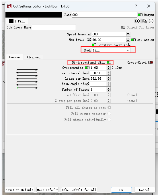
2.2 After adjusting the above data, click "Edit Material Setting" (settings for patterns)
To adjust the “Mode” parameter ------ “Fill” refers to the pattern (grid) fill color. Note: If choose “line” here, the machine will only outline each grid.
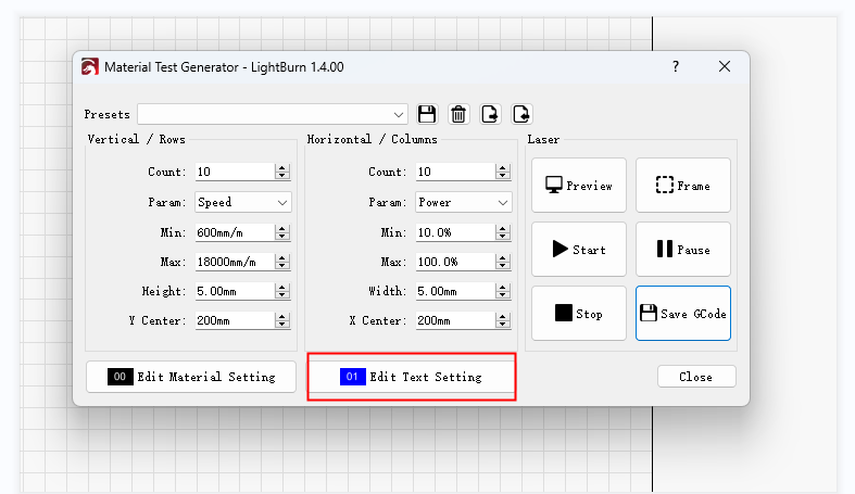
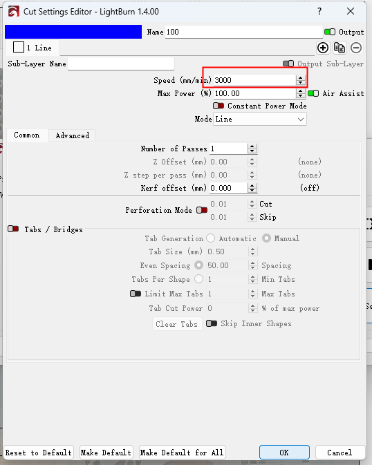
2.3 After adjusting the pattern settings, click "Edit Text Setting" (settings for text outside of the pattern)
Step 3 Preview and Run
After adjusting all parameters, Click “Preview”, then you can check if the pattern needs to be adjusted
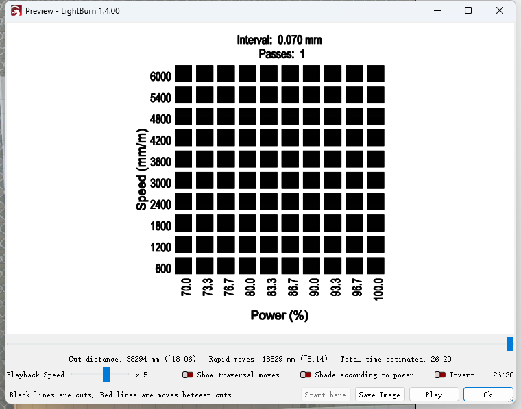
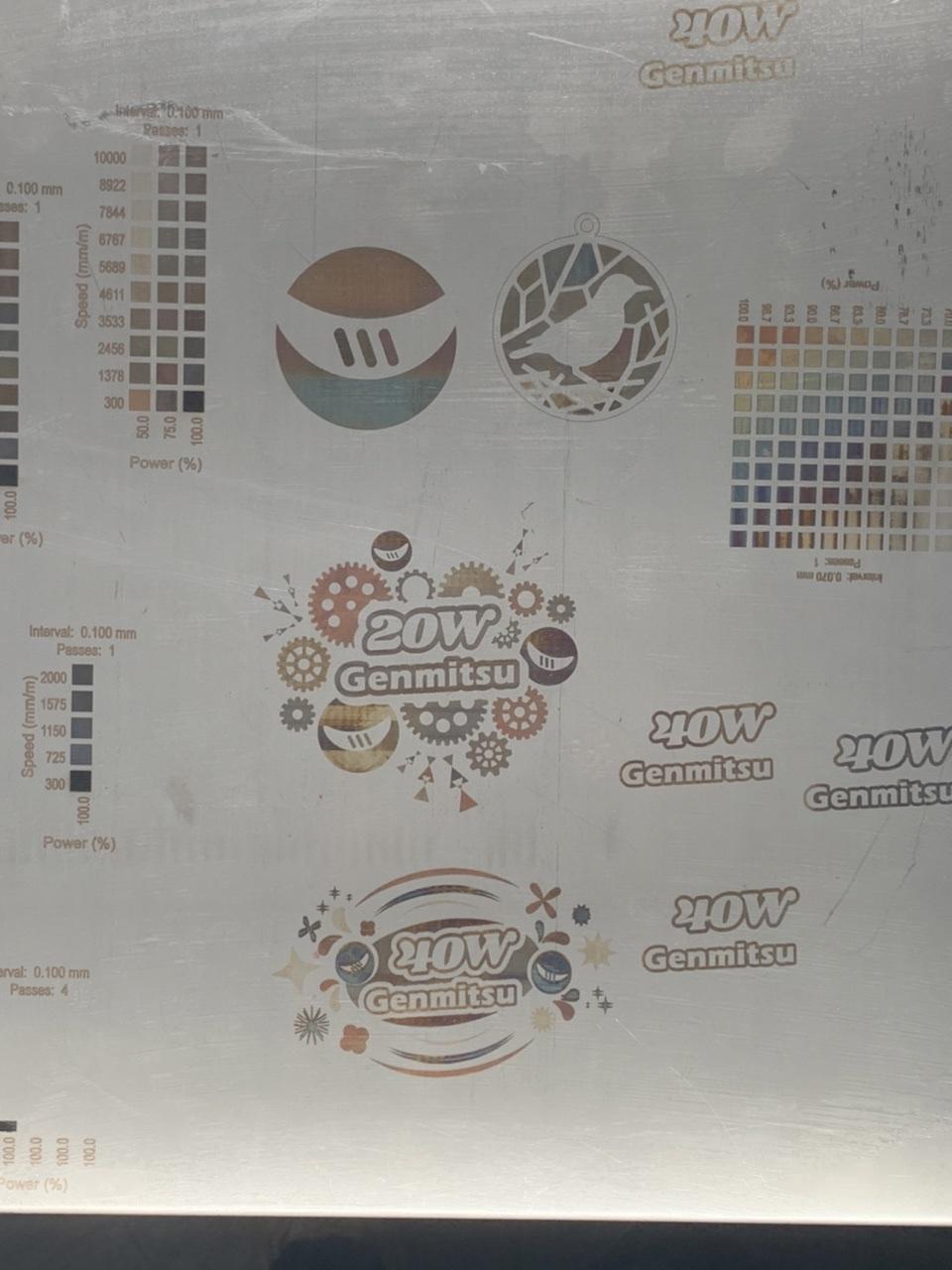
The example below shows what you can expect after running a material test. On the left side, you can see a range of speeds, and on the bottom you can see a range of power levels. At the top, you can see the settings for interval, passes, and frequency.
Step 4 Saving and Exporting
At the top are buttons allowing you to save, delete, export, and import presets. There is also a dropdown allowing you to select a saved preset. This is useful if you have custom settings you like to run frequently, for instance a smaller test pattern you want to use on metal tags or a range of settings you want to test on different woods.
To access presets for the material test, go to File > Open prefs folder And then in that opened directory the presets will be under ./presets/material_test_presets.lbmt
Color Engraving on Stainless Steel
Diode lasers can be effectively utilized for color engraving on stainless steel. The underlying mechanism involves the absorption of the laser’s blue light by the nickel and carbon present in the stainless steel’s surface layer. This absorption process generates heat, momentarily displacing the nickel and carbon. Consequently, the iron within the material, now heated, oxidizes instantly, leaving a distinct mark.
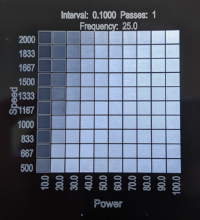
To achieve varying color effects, it is recommended to conduct material testing on stainless steel, adjusting the laser’s speed and power settings. This process should enable the creation of a comparative parameter table.
Once the table is prepared, select your preferred color from the reference table. Input these parameters into the design you wish to engrave. This method should allow you to achieve the desired color engraving on your stainless steel design.
The below picture is shown as an example. Note that the color effect can vary based on the material used, and significant changes can occur with alterations in power and speed. Therefore, it is advised to conduct material testing and refer to your own post-testing parameters for optimal results.