Genmitsu 3018-Pro 5.5W Laser Module User Guide

Introduction
Dear customer,
Thank you for purchasing the SainSmart 5.5W laser module. This blue 5.5W diode laser has a wavelength of 445nm, and is especially designed for use with our Genmitsu 3018-PRO, and 1810-PRO.
You can also get help and support in our Facebook group (SainSmart Genmitsu CNC Users Group, https://www.facebook.com/groups/SainSmart.GenmitsuCNC).
In addition, as always, competent SainSmart support is available to you at the e-mail address support@sainsmart.com
Safety Guideline

Always exercise safety and caution when working with laser marking systems. Consider the listed recommendations to minimize risk:
- You must be at least 13 years old to operate the laser engraver.
- Direct exposure to the laser beam can cause severe burns and eye damage. Ensure that you are wearing proper laser safety goggles when working in the vicinity of the laser equipment.
- When you focus the laser do so only on the lowest power setting.
- Keep a fire extinguisher nearby since use of the laser may lead to an unexpected fire.
- Never leave an operating laser unattended.
- Fumes and smoke generated during the engraving/cutting process must be extracted from the room as some can be poisonous; make sure there is a ventilated system to the outdoors.
- Make sure the cutting area under the laser is metal or non-flammable.
- Ensure that the room or area you are operating the laser in is sufficiently labeled to prevent someone from unknowingly walking into an active work area.
- Be sure to disconnect the power when cleaning, maintaining or servicing the laser equipment.
- DO NOT stare at the bright and intense light appearing during the engraving process. Doing so can cause serious eye damage.
- Never use the laser except for the purpose intended.
SainSmart does not accept any responsibility or liability for any use or misuse of the Laser.
What's in the Box
Name | Size/Type | Picture | QTY |
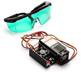
Laser Head and Control Module | Black Module Version | 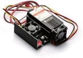 | 1 |
Safety Goggles, adjustable | Green |  | 1 |
3 Pin Connection Cable | 60 cm |  | 1 |
T Nut 10 M3 | M3 x 10 mm |  | 2 |
Hexagon socket screw | M3 x 6 mm |  | 2 |
Descriptions of Primary Components
Laser Head
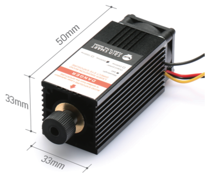
This is a 5.5W blue diode laser with a wavelength of 445nm. In order to ensure sufficient cooling, the laser is mounted in a heat sink, which is additionally equipped with a powerful yet quiet cooling fan.
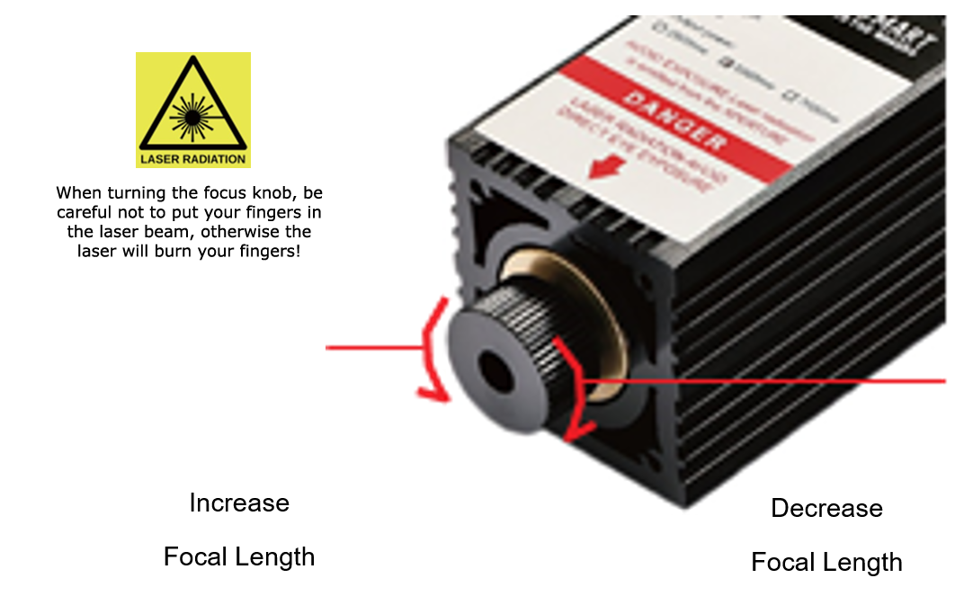
The laser has an adjustable focus. This is adjusted by turning the knurled knob mowing the shaft which contains the focusing lenses, in and out of the body.
The laser head is connected to the laser control unit by two cables of about 30 cm length each. The yellow/black cable provides the connection to the laser diode. The red/black cable is for connecting the cooling fan.
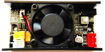
Laser Control Module
With a matching Black coloring, this laser module is meant only for the Laser head of the same color.
This component acts as an interface with your CNC, containing all the necessary electronics for processing the PWM signal coming from your CNC, resulting in the laser being supplied with the required voltage at the right time to meet the demands of your projects.
The Laser Control Module is meant to be mounted to the aluminum extrusion profile on the back of your X axis of your CNC by means of the supplied T nuts and M3 screws. A 2.5mm hexagon wrench is required for mounting those screws.
Oriented based on the image above, the left side of the Laser Control Module is where you plug in the yellow/black wire from the Laser Head, and the Red/Black wire from the Laser Head cooling fan.
The Red/Black wire plugs into the White port marked 'Fan+'
The Yellow/Black wire plugs into the Yellow port marked 'LD+'
Above these two ports is a LED which is on when the laser has power.
On the other side there is a red 3-pin connector for the input signals ‘12V’, ‘PWM’ and ‘GND’ which looks like this:
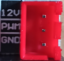
This is connected via the supplied 3-pin connection cable to the corresponding red 3-pin port on your 3018 Pro CNC Controller. Before switching on for the first time, make sure that the signals are connected to the correct pins.
In addition to everything mentioned so far, there is also a white toggle switch that looks like this:
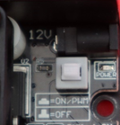
This switch is very important, because many users mistake this as an on/off switch, but in actuality this switch toggles PWM control on and off. PWM control is what your CNC uses to control your laser, so you want this on toggled to On/PWM at all times. If this is toggled off, your laser will fire at full strength at all times, with no way to control it.
To the right of the white toggle switch there is also another SMD-LED. This SMD LED, marked ‘POWER’, lights up red when the laser control module is switched on.
The additional 4.0mm/1.7mm DC Power Jack can be used with an external power supply if necessary. However, if the laser module is used with the 3018 Pro or 1018 Pro, you should not have this plugged in, as the laser will draw all the power needed directly from your CNC board.
Mounting the Laser in a Genmitsu 3018 Pro CNC
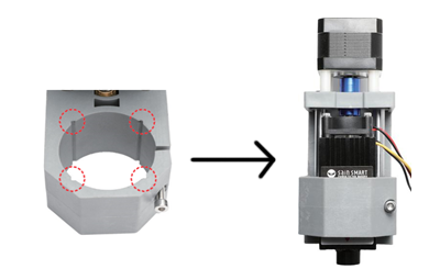
The first thing you should do is disconnect both sides of the electrical connection to the spindle motor. Then remove the spindle motor from the motor mount. Do not operate the SainSmart 3018-PRO with both the laser and the spindle motor connected!
Slide the laser head into the motor mount so that the corners are in the slots of the motor mount and the cooling fan of the laser head pointing upwards. Position the laser head so that the lower edge of its heat sink is about 60mm above the work piece. At this distance, it is usually very easy to adjust the optimal focal point of the laser at a later time. Tighten the clamping screw on the motor mount, do not over tighten, it just needs to be secure.
The laser head has two 2-pin connection cables, one for the power supply of the cooling fan and one for the laser diode. Make sure that both cables are connected to the yellow and white pin socket of the laser control module as described above.
The laser control unit can be mounted on the rear of the CNC machine on the aluminum profile to the right of the control unit of the CNC machine using the M3 T nuts and screws supplied. Make sure that the cables to the laser head can move freely so that the laser can move in all axes to the limits of its travel.
Connecting to your CNC Controller
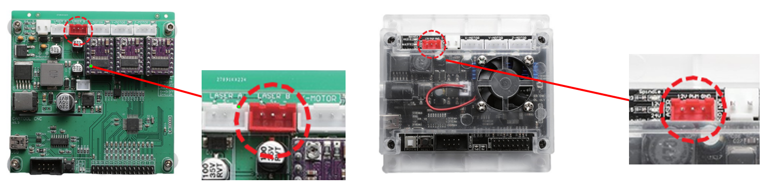
The above images show the two varieties of 3018 Pro boards currently in circulation. In either case, the red 3-pin port is connected via a wire included with your module which connects on the other end to a red 3-pin port on your Laser Control Module.
Startup Warning!
Powering on the router and connecting the USB Cable can cause the laser to fire for a short while, so ensure you are wearing the safety goggles. This can also burn the stock depending on what you are using so it makes sense to put something non burnable under the laser beam before turning the router on and connecting to any software.
Installing LaserGRBL
LaserGRBL is a free program which works with Grbl based routers fitted with a Laser and Laser Engravers. It will be used here to assist with setting the Laser Focus though is capable of both sending GCode and converting images to GCode for Laser Engraving It can be downloaded from https://lasergrbl.com/download/
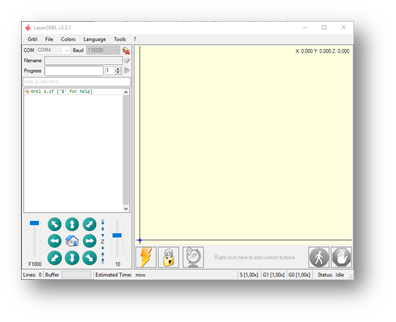
After installation and connecting to the router the screen should look like this:
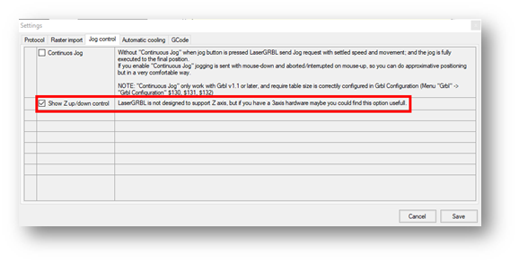
Enable Z Axis Jog
This feature is disabled by default, but it is useful for Genmitsu CNC's because it already has a Z axis. To do so, select ‘Grbl' > ‘Settings” and click on the ‘Jog Control' Tab. Make sure the ‘Show Z up/down control” box is ticked and save.
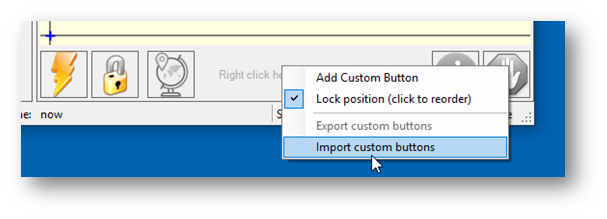
Adding Custom Buttons
Download the file CustomButtons.gz from this page.
Right click on the text ‘Right click here to add custom buttons’ in the Buttons pane and select ‘Import Custom buttons’. In the Open Window select the downloaded file and click Open. The dialog box of Import custom button will appear.
In the ‘Open’ window, select the downloaded file and click the ‘Open’ button. Now a short dialog is displayed for each of the three additional buttons. You can now select for each individual button contained in the archive file whether it should be imported or not. Select ‘Yes’ for each button.
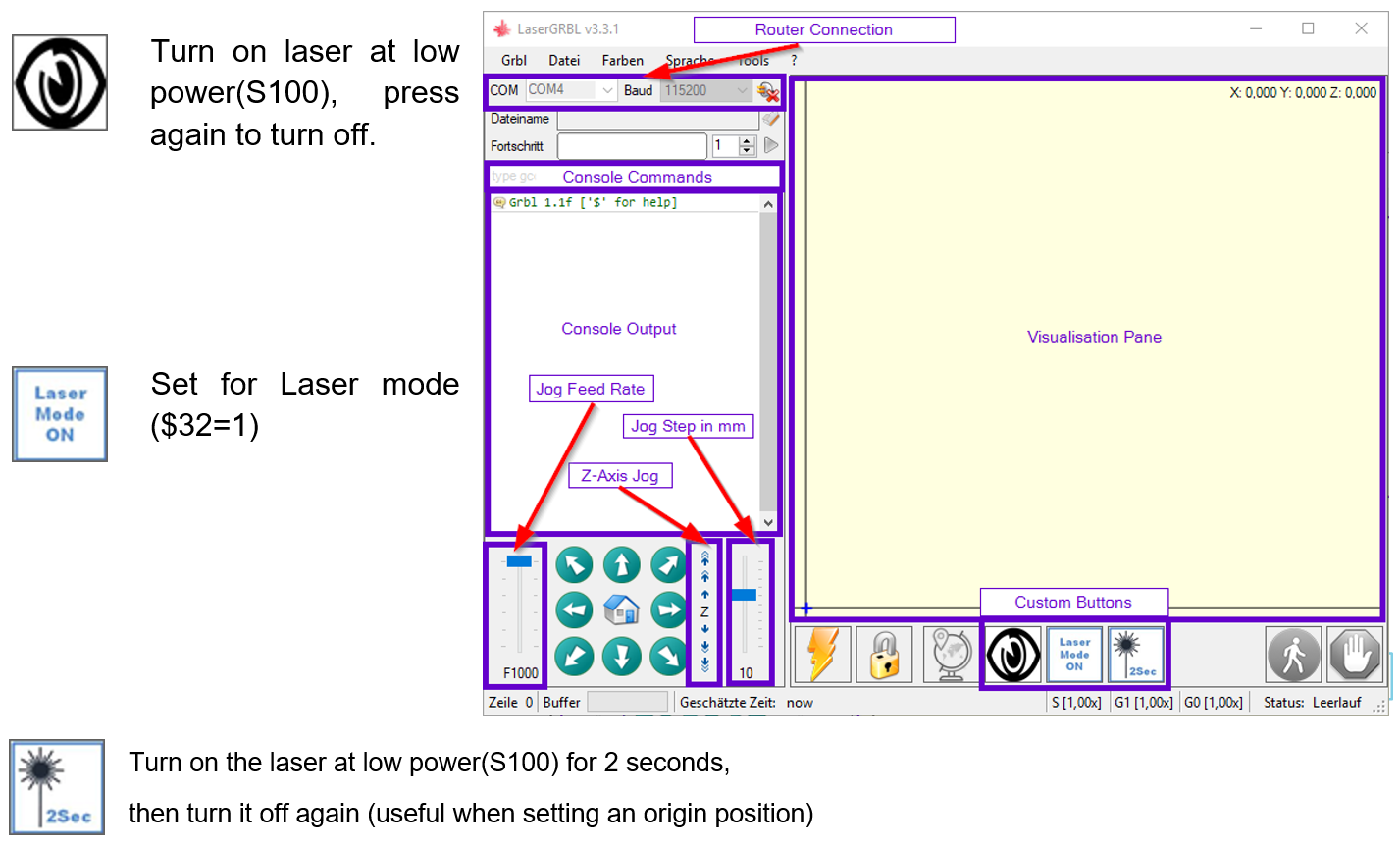
The LaserGRBL window should now look like this:
Focusing The Laser
To cut or engrave efficiently we want the laser beam to be tightly focused into the smallest possible point at the top of the stock. Make sure the On/Off button on the laser module is set to ‘ON/PWM” (depressed). Do not forget to wear the Safety Googles.

Place something of known thickness above the stock which will not burn and jog the Z axis so the bottom of the Laser Head Heat sink is 60mm from the top. This measurement will make it easier to repeat the focusing on different stock heights or after remounting the Laser of the stock. Or allow the positioning of the laser on the Z axis to avoid having to refocus every time. Focus is adjusted by turning the focusing knob to move the lenses in the shaft in and out of the Laser Head.
Next use this button to turn on the laser at low power:

With the laser on at low power, you can turn the focusing knob on the laser head as shown below to decrease or increase the focal length:
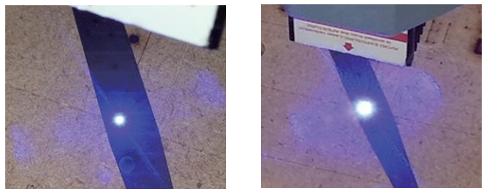
Adjust the focusing knob to create the smallest possible dot at the center of the laser beam's contact point. The right image is not focused, the left one is focused:
With your laser focused, pressed the Laser Fire button again to turn it off.
Enabling Laser Mode
When using a laser in conjunction with a GRBL based CNC router such as the 3018 Pro, there is an important setting in GRBL which lets the CNC know what mode you want to be in. This setting is $32 and it can be edited in your command console by typing $32=1 to turn on Laser Mode, and can be turned off by typing $32=0.
Clicking the middle custom button ‘Laser Mode On’ will also toggle Laser Mode between being on and off. This is permanently stored on the 3018-PRO motherboard until it is specifically changed, so make sure to turn it off when you are done.

The major effect of setting Laser mode on is that the router will turn off the laser when it is making positional moves. If not set this can result in unwanted lines on your engraving as the Laser is positioned to the next cutting point.
For use with Non-SainSmart CNC's
Please refer to the manual of your CNC for assembly instructions. Pay attention to the required cable lengths of the supply lines to the laser head and the laser control module. Depending on the machine purchased, you may need to check that individual pins match, or source longer wires.
Power
The laser requires a 12VDC power supply capable of providing at least 3A. If the control module of your CNC cannot provide this, you will need an external power supply. In this case, the +12V lead of the 3-wire cable which is connected to the red pin socket of the laser control module must not be connected to it. The power supply of the laser must then be provided by an external DC power supply unit with 12V and at least 3A. The power supply unit is connected to the laser control unit via the 4,0mm/1,7mm DC jack, located above the ON/OFF switch.
PWM Signal
This laser uses a standard PWM (0 to +5V) signal for control. The Laser is on when the PWM Signal is +5V and is off when the signal is 0V.