Genmitsu Laser Rotary Roller Engraving Module User Guide
 Updated
Overview
1. Application: This machine can work with a number of different Sainsmart machines to engrave on materials with a cylindrical shape.
2. Engraving Size: Cylinder diameter 22-125mm, length 20-220mm, material length/material diameter>1.0
3. The Rollers can be set at 5 different distances, each one 15mm further than the last. The adjustable range is 30-90mm.
4. Motor: NEMA17 34mm Stepper Motor; Phase Current: 1.33A
5. Pulse Parameter Setting: 84PULSE/mm
6. Maximum Load Weight: 5 KG
7. Dimensions: 270mm*145mm*65mm
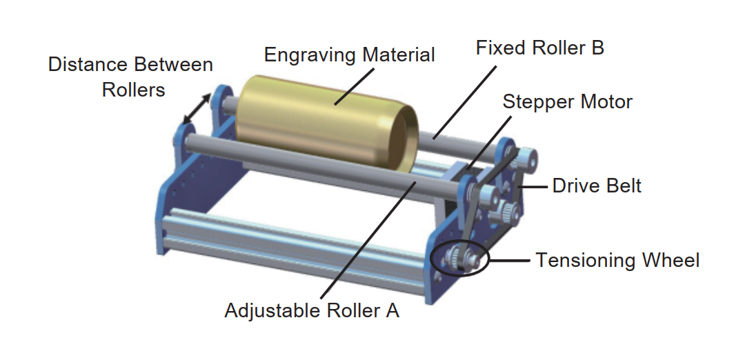
Note: The front roller is a fixed roller and cannot be moved, only the rear roller can be adjusted.
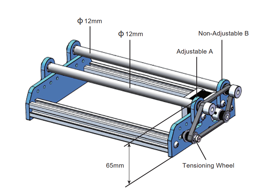
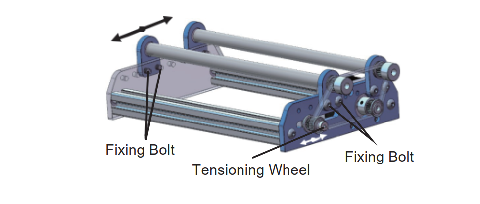
Step 1: Adjust the Spacing Between Rollers
1. Place the engraving material between the two rollers and confirm whether they are far enough apart to support your cylinder without lifting it up too high. Generally, the lower the cylinder sits, the better.
2. When the distance between rollers is not correct remove the 4 fixing bolts at the left and right ends of the adjustable support shaft, and rotate the fixing bolt of the tensioner one turn counterclockwise.
3. Move the adjustable roller to adjust the distance between it and the fixed roller according to the actual situation. When the distance is appropriate, tighten the adjustable roller fixing bolts.
4. Move the tensioning wheel assembly to make the synchronizing wheel under tension, and tighten the fixing bolts.
5. Rotate one of the rollers by hand, and check whether the other roller and the synchronous wheel of the motor rotate together as one. The movement should be smooth, if it is not you may need to reduce the belt tension slightly.
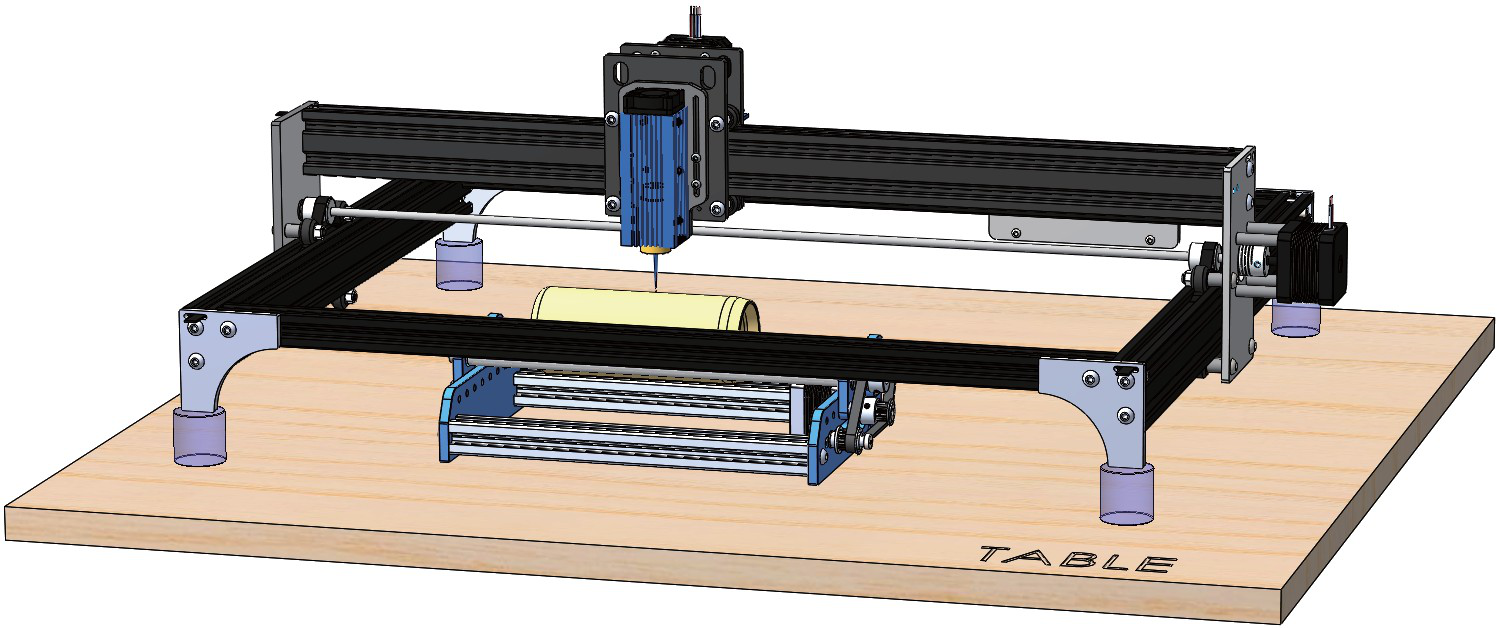
Step 2A: Installation Guide for if your Machine has One Y-axis stepper motor
Step 2A is meant for machines that only have a single port/stepper motor, such as the 3018 Pro, 3018 Prover, LE-1620 and LE-5040
1. Place your CNC or laser engraver on a flat surface and unplug the Y-axis stepper motor cable
2. Place the rotary axis in an appropriate position on the table, and connect the machine Y-axis motor cable to the rotary axis stepper motor.
3. Adjust the position of the rotary axis so that your cylinder will be parallel to the X-axis and perpendicular to the Y-Axis.
Step 2B: Installation Guide for if your Machine has Two Y-axis stepper motors
Step 2B is meant for machines that use two stepper motors for their Y-axis, such as the 3020 Pro Max, LC-60A, and 4030 PROVerXL.
1. Place your CNC or laser engraver on a flat surface and unplug the X-axis stepper motor cable
2. Place the rotary axis in an appropriate position on the table, and connect the machine X-axis motor cable to the rotary axis stepper motor.
3. Adjust the position of the rotary axis so that your cylinder will be parallel to the Y-axis and perpendicular to the X-Axis.
Step 3: Install, Connect to and Configure LaserGRBL
1. If you do not already have LaserGRBL installed, download it from here.
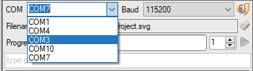
2. In LaserGRBL select your com port, set your baud rate to 115200
, and press the connect button to the right of the baud rate value. If successful, the console should show "grbl 1.1f" or grbl 1.1h"
3. There is a bar that says "type gcode here," select it, type the following depending on which step you followed previously:
- Regardless of what step (2A or 2B), type $$ into the bar and hit the enter key. When you do this you will see a long list of values printed out. You will want to save this list in a text document somewhere so that you know what to change $100/$101 back whenever you will disconnect the rotary roller.
- If you followed Step 2A then you will want to type $101=84 into your console and hit the enter key.
- This will alter the steps/mm for the Y-axis so that it is configured for the rotary roller.
- If you followed Step 2B then you will want to type $100=84 into your console and hit the enter key.
- This will alter the steps/mm for the X-axis so that it is configured for the rotary roller
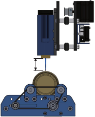
Step 4A: Focusing your Laser with a Fixed Focal Length
1. In order to bring the laser into focus with a fixed focus laser module, you will need to take the metal focusing tool and stack flat objects under the rotary axis until the distance between the laser and the cylinder is the length of the metal focusing tool.
2. Test fire your laser at a low power, 5% or less, and make sure that your laser is focused to a tiny point.
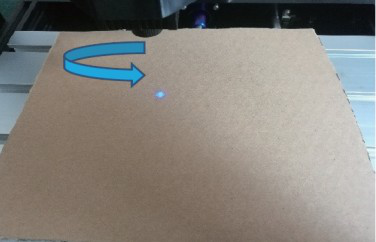
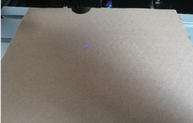
Step 4B: Focusing your Laser with an Adjustable Focal Length
1. For this laser type you will need to have the laser firing while you focus your laser point on the stock cylinder. Do not fire at any more that 5% power.
2. With the laser visible, twist the round black knob at the bottom of your laser clockwise to adjust the focus of the laser. Your goal is to make the laser point as small as possible.
If you over-focus then twisting clockwise to go backward can be used.