How to Use Your Rotary Axis for the LE5040 with LaserGRBL

What You Will Need
- Genmitsu LE5040 CNC Laser Engraver Machine
- Genmitsu LE5040 Laser Rotary Roller
- LaserGRBL
- Cylindrical Stock Material
Before You Start
- This guide builds off of the foundation already established in the LE5040 Quick Start Guide with LaserGRBL . It is strongly suggested that you go through that guide before going through this one.
- Section 3 of that guide, in regards to custom buttons, is of particular importance, so make suire to download and install those buttons into LaserGRBL.
- In addition, make sure to follow through with all instructions on installing and positioning your rotary axis.
Step 1: Add Another Custom Button
To make life with the rotary axis easier, another custom button has been made to add in to LaserGRBL in addition to the ones created for the Quick Start Guide. You can download this button and add it just like the others from this download link. The button will look like the below and work as follows:

Toggle Rotary Mode
This button modifies two different firmware parameters:
$101 is set to 84 in accordance with the user manual that comes with the rotary axis. When the button is clicked a second time, $101 reverts to the original value of 80.
$121 is set to 750 because the acceleration value of 2000 (as set by the "Tune Your Laser" button) because too high of an acceleration value can move your stock material to laterally shift, ruining your engraving. When the button is clicked a second time the value is reverted to 2000.
Step 2: Orienting your project in LaserGRBL
When you first import your image that you want to engrave on the stock cylinder the first thing you will want to do aside from tailoring all the parameters to suit your needs is to rotate the image so it is oriented as you want to.
Assuming that you have installed the rotary axis as instructed in the guide, your setup should look something like the image below with your stepper motor/belt and pulleys all on the right hand side:
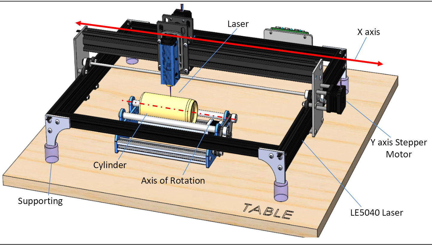
From this perspective you can consider that the right is the top and the left is the bottom. There is nothing in particular stopping you from flipping the rotary axis around, but please note that the orientation in LaserGRBL would have to be reversed as well.
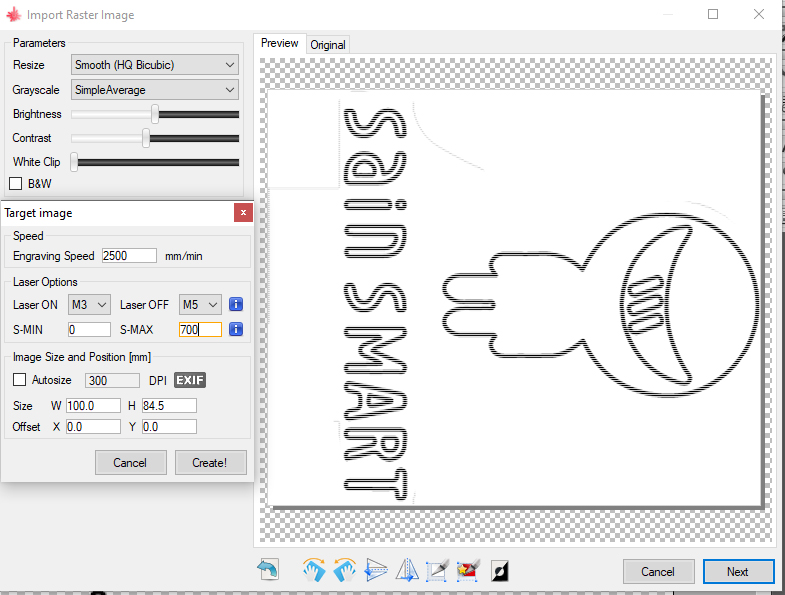
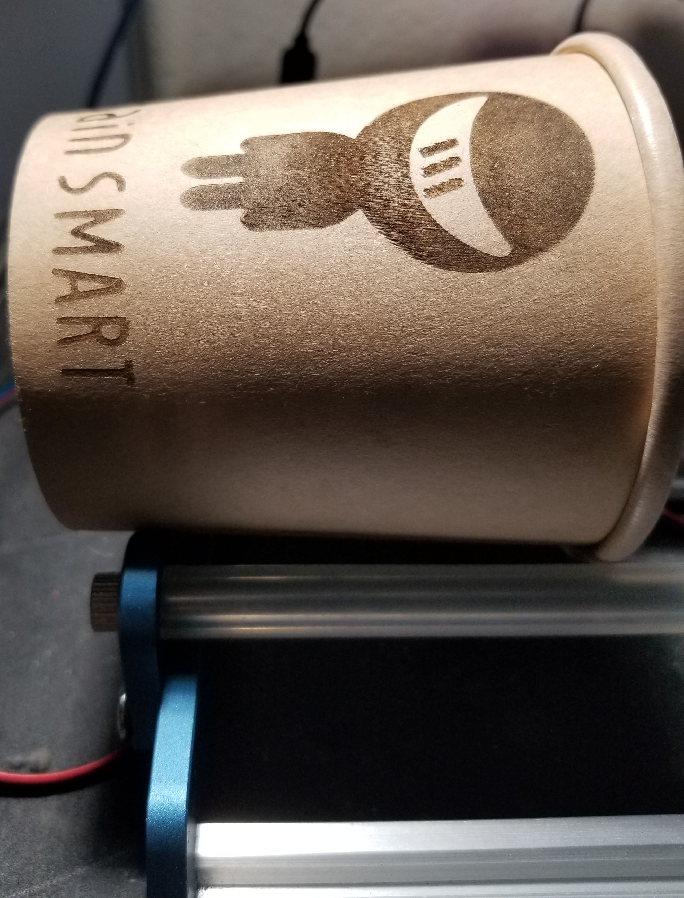
As you can see with the image above, taken from LaserGRBL, the engraving has been rotated clockwise by 90 degrees so that it will engrave in the proper orientation. The end result from this orientation can be seen below:
Step 3: Sizing Your Engraving
Once you select "Next" on the Import Raster Image page, you will see a new window which is called "Target Image". This window is important because it establishes:
- The speed the LE5040 will engrave at (Engraving Speed between 0 and 5000)
- The power the LE5040 will engrave at (S-Max with a value between 0 and 1000)
- The size of your engraving.
What is important to focus on now is the latter, because this is the only chance you have to alter the size. In the case of the image above, the length of the cup from the lip to the bottom edge was measured in mm, subtracted a bit to give the engraving a little extra room on top and bottom and the width auto-sized accordingly.
This is fairly self-explanitory but the main reason to touch on the subject of sizing is because you can intentionally or not have an engraving roll up into itself. This can occur when the width of your engraving is greater than the circumfrence of your cylindrical stock material.
Step 5: Placing Your Engraving
The standard for LaserGRBL is that the bottom-left corner is the starting point for the laser, so wherever the laser is located, the image will be engraved above and to the right of that point.
Once you have selected that point, go ahead and make sure to click the globe button:

This will zero everything out and ensure that your project will engrave where expected. From there, in order to make sure that the engraving will be placed where you want it to, try using the "Frame Project" custom button.
This will trace the outer rectangular perimeter of your project while the laser is firing at .5%. You can use this to make sure that you like where the engraving will be placed and make adjustments accordingly.
After this, you are all set! Make sure to double-check that your laser is properly focused and get started!