4th Axis - Rotary Machining Guide
 Updated
AUTODESK Fusion 360
Introduction to Rotary 4th Axis machining with your Genmitsu series CNC machines and AUTODESK Fusion 360.
Rotary machining can be accomplished in a variety of ways, in the beginning of this guide we will focus on “Wrapping” or “Indexed” workflows.
The wrap option in Fusion 360 leverages the 4th axis on your machine and can be useFd with 2D Adaptive, 2D Pocket, and 2D Contour. It allows these toolpaths to be wrapped around cylindrical models, which is machined using a rotary axis
Getting Started
Fusion 360
Sainsmart has created rotary post processors for Autodesk Fusion 360 and is available for download.
This includes two rotary post processors:
1. Genmitsu CNC Warp X to A: Wraps X moves to A moves. Toolpaths will be wrapped around the Y axis. Units (G20 or G21) will be determined from the document units in Fusion.
2. Genmitsu CNC Warp Y to A: Wraps Y moves to A moves. Toolpaths will be wrapped around the X axis. Units (G20 or G21) will be determined from the document units in Fusion.
There are two options for how to install the posts:
1. Install post processor to a Cloud library in Fusion 360
2. Install a personal (locally saved) post processor in Fusion 360 CAM
V-Carve
Sainsmart has created rotary post processors for V-Carve and is available for download.
Creating G Code
There are a few CAM software packages with rotary capabilities that have documentation for generating tool paths.
Fusion 360: 4th Axis Wrap Toolpath
If you want to perform indexing operations in Fusion 360, you can set up a different tool orientation for each operation within a single setup.
VCarve Pro: Rotary Machining and Wrapping
Aspire: Rotary Machining and Wrapping
● Ensure you have downloaded and installed the rotary post processors (see section 2) for your CAM software.
● Select the appropriate post processor to wrap either your X axis or Y axis moves to A axis moves.
Workpiece Setup
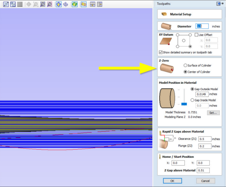
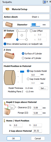
If using VCarve Pro or Aspire, in your Material Setup settings, ensure your Z-Zero is set to the Center of Cylinder.
Only use the Surface of Cylinder if you will be manually setting all work offsets. Using the Auto Z Touch Plate will set work offsets to the center of the cylinder.
Creating a Rotary Toolpath using Vectric Vcarve Desktop
Machine Setup
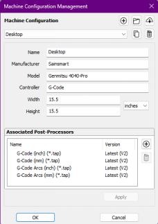
Select your Sainsmart Genmitsu CNC - In this case your Genmitsu 4040-Pro. Apply the associated Post Processors listed and select OK.
Stock Material Setup
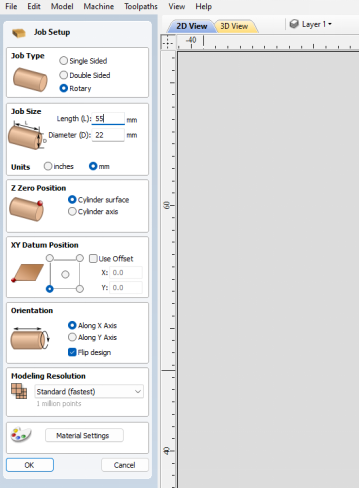
Select Rotary and input your material dimensions and orientation.
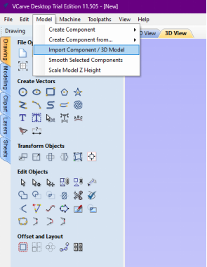
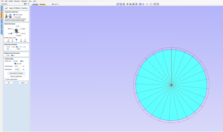
Import your 3D Model
Select your Model Orientation and Rotary setup
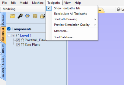
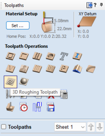
Toolpath Creation
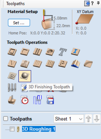
Select Show Toolpaths Tab
Material Setup
3D Roughing Toolpath
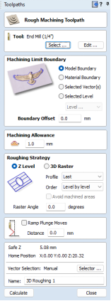
Configure Rough Toolpath settings
Setting Tool by selecting a preset tool from the library, or inputting your own tool and adding parameters.
Set Working and Movement Boundaries
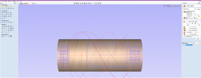
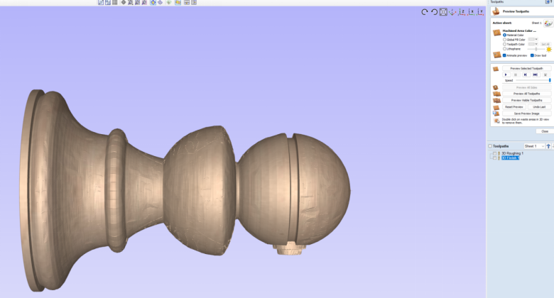
Select OK to calculate toolpaths and generate a preview
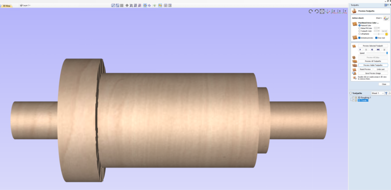
Configure Finishing Toolpath

Setting Tool by selecting a preset tool from the library, or inputting your own tool and adding parameters.
Set Working and Movement Boundaries
Select OK to calculate toolpaths and generate a preview
Select your Post Processor
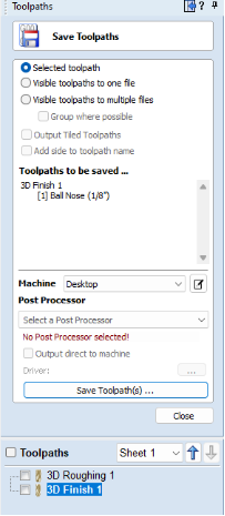
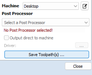
Save and Export you File
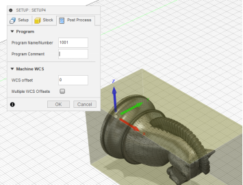
If using Fusion 360, your WCS needs to be located at the center of your part
Only use a different WCS location if you will be manually setting all work offsets.
4th Axis Rotary - Autodesk Fusion 360
*Requires Manufacturing Extension
Starting your first project
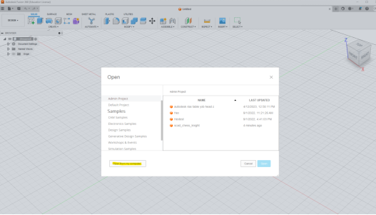
Select File >> Open and navigate to the model you wish to import.
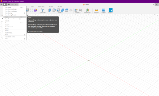
Select “Open from my computer”
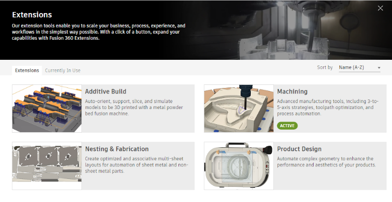
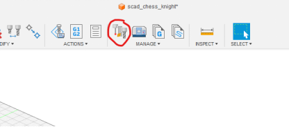
Top right corner of the window select the extensions
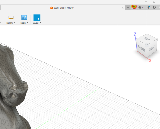
Select Machining
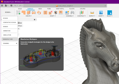
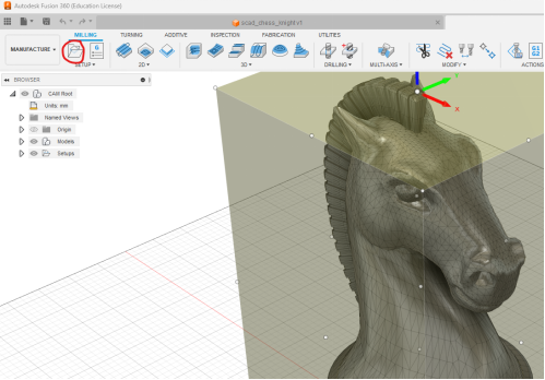
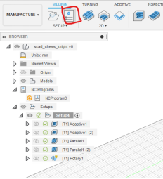
Opening the Manufacturing Interface
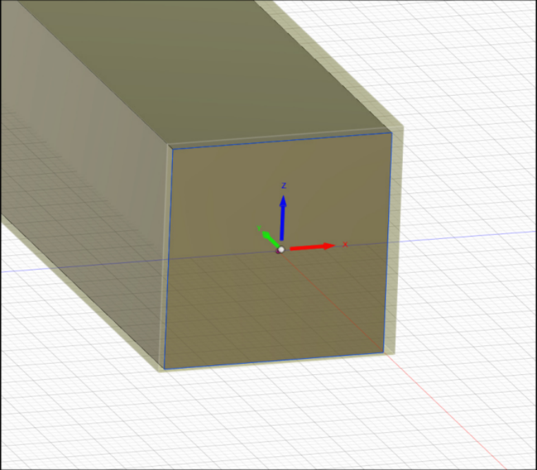
Stock and Coordinate System Setup
Set your Work Coordinate System
Select Z Axis Plane and X axis
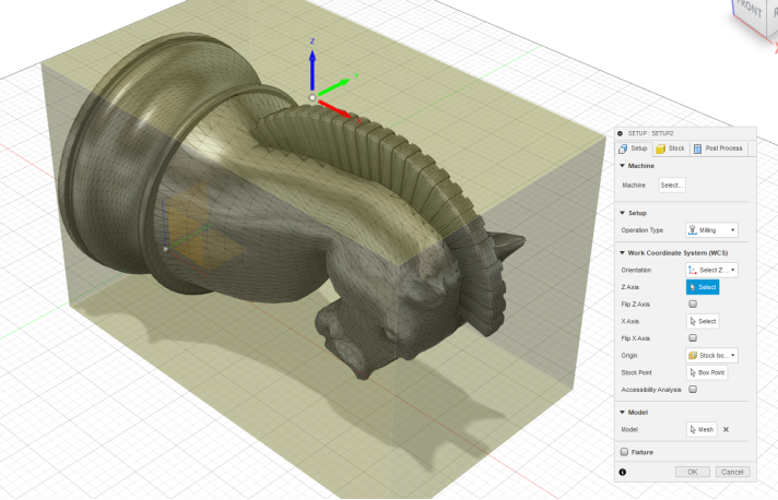
Your X axis needs to match the orientation of your rotary machine configuration.
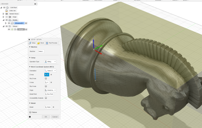
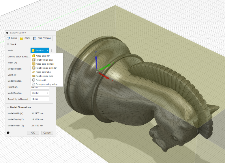
Select either Fixed Size Box or Cylindrical mode depending on the Stock material being used.
Rotary Tool Path creation - Roughing and Finishing
Go to the Post Processing Tab
Select your Post Processor - GRBL MM or GRBL IN ( Genmitsu GRBL )
Tool Settings
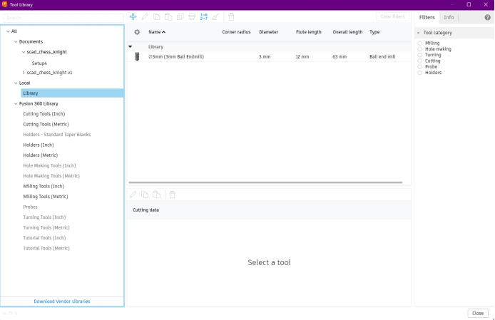
Go to the “Tool Library”
Here you will add your desired Tools for this project. After you have created and added a tool it will be saved here for use with other projects.
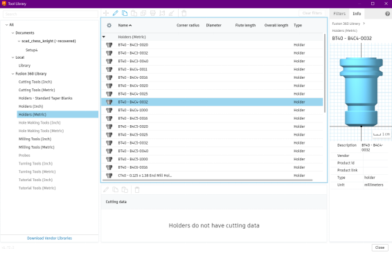
After you have added your first tool you will need to add the Tool Holder. Right click on the Tool BT40-B4C4-0032 for the standard factory selection.
Toolpath Creation
Choose Adaptive Clearing under the 3D Toolpath selection
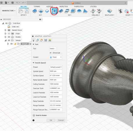
From here you can modify your toolpath settings to suit your workflow
Set Boundaries for Tool Movement > Open Machining Tab
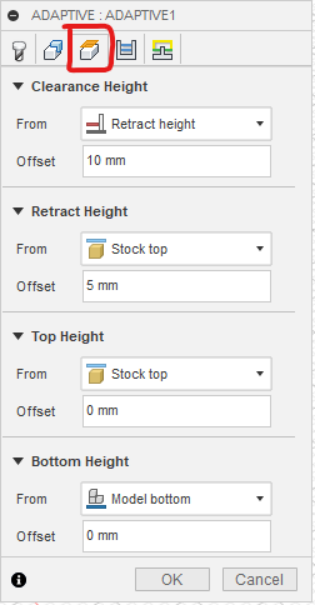
Define your Machining Parameters. Default values are established based on the generic tool interfaces.
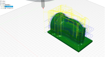
After select “OK” The system will generate the toolpath and allow you to simulate the processing results.
Apply your previous toolpath by copying and pasting for the other side of the model.
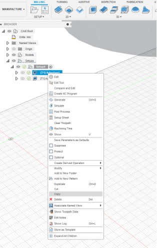
After both Toolpaths have been created you can Right Click on the Setup and select “Simulate”
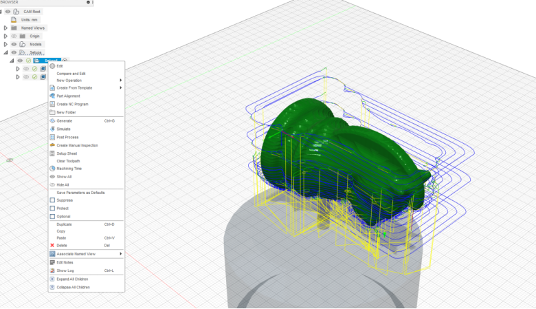
Preview your workflow operations and make any adjustments as necessary.
Create the Finishing Toolpath by selecting the Multi-Axis menu and selecting Rotary.
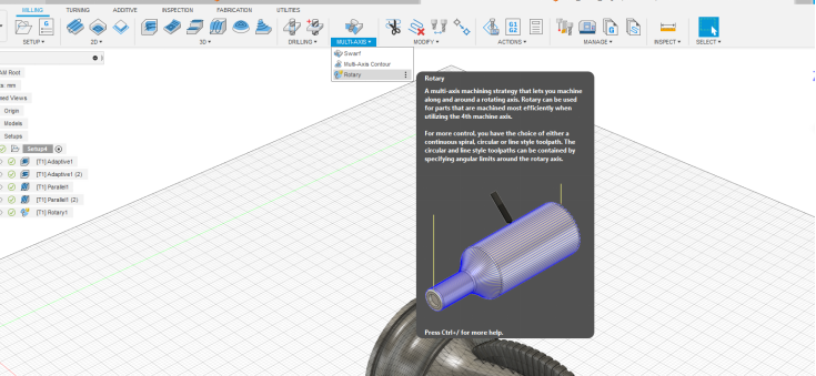
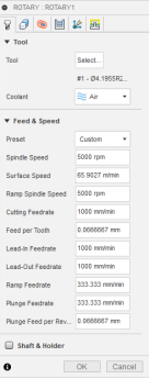
Like previous toolpaths, select your tool and set your standard values.
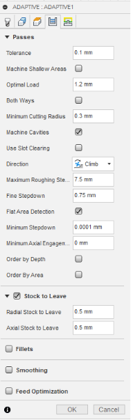
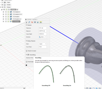
Select the Passes Tab
Adjust Stepover and Tolerances as needed. It is recommended to enable the Smoothing option by checking the box.
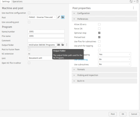
Generate your Simulation. Verify toolpaths are correct and proceed with saving your file by navigating to NC Program
Select the Post Processor
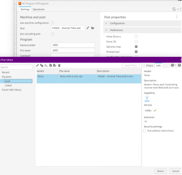
Verify settings are configured correctly
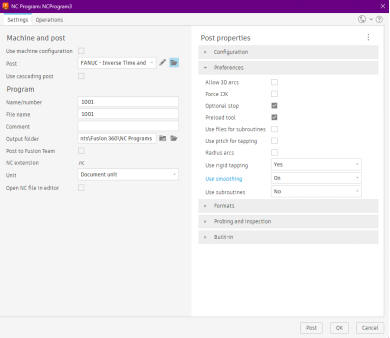
Configure your output folder, you are ready to save and export your work file.