Genmitsu 3018 Pro Assembly Notes

This guide is taken from the works of Jim Kortge
Introduction
This document was created as an aid to those assembling a SainSmart Model 3018-Pro CNC Router. With it, we hope to help you assemble your machine and get it up and running in the least amount of time, and with the fewest mistakes.
Unpacking the Machine
Carefully take all of the parts out of the shipping box and lay them out on your work surface. Referring to the packing list in the User Manual, pages 2 to 5, confirm that you have all of the parts shown on the list, and that none of them are missing, bent, nor broken. If there are any parts issues, contact SainSmart Support: support@sainsmart.com
Mechanical Assembly
Assembly of this machine is best done on a smooth, hard surface that is flat, and large enough to accommodate the size of this machine. A surface size of 600 mm X 600 mm (2 feet X 2 feet) is suggested as a minimum.

It is highly recommended to use Locktite 242 Blue Thread Locking compound (or equivalent) on all bolts during the assembly of this machine to prevent bolts from becoming loose due to vibration.
Mechanical assembly of the machine starts with the base as shown in the User Manual, page 6. The left and right sides are bolted to the front plate (Bakelite-A) containing a bearing. Use a mechanics square or 123 blocks to assure the sides are 90 degrees to the front plate. Next, attach the two guide rails to the front plate, but don’t completely tighten the bolts. Slide the sliders (2 per side) onto the guide rails, with the holes oriented as shown in the User Manual. Next, bolt the rear plate (Bakelite-B) to the side rails, but don’t completely tighten the bolts, then add bolts to secure the guide rails to the rear plate. Again, using a mechanics square or 123 blocks, tighten the side rear bolts, and then, the guide rail bolts in the front and rear.
After the base is assembled, the Y-drive screw with stepper motor and Aluminum Tables are installed.
Next, install the Coupling onto the shaft of the Stepper Motor. If available, use a small amount of “thread lock” on the threads of the Stepper Motor Coupling Set Screw. Then install the Stepper Motor to the rear of the Base Assembly. The Stepping Motor electrical connector should be oriented to the right, when looking from the front of the machine.
Next, take the Lead Screw and screw it into the Nut Seat part, on the side away from the front notch. Once started, take the Brass Anti Backlash Nut and its compression Spring and hold them in a compressed condition in the notched opening of the Nut Seat while continuing to screw in the Lead Screw until the Brass Anti-backlash Nut assembly is engaged on the threads. Continue screwing the Lead Screw until it is approximately centered on the Nut Seat.
Slide this Lead Screw assembly into the front bearing, then back it into the open end of the Coupling. Install the Lead Screw end of the Coupling Set Screw (use “thread lock” if available) and tighten this Set Screw. Rotate the Lead Screw by hand to test that it is turning freely and on axis, then tighten the other set screw.
Referencing the Table Installation photo in the User Manual, page 7, install the 30M5 T-nuts on to the 4 Sliders and to the Nut Seat. Leave them with their bolts just engaged in the threads of the T-nuts, so that they are loose. Orient the T-nuts as shown in the photo, with the long direction aligned with the long direction of the Base Assembly.
Orient the Aluminum Profile piece with 4 slots up, and carefully slide it on to the T-nuts, from left to right. The Lead Screw will need to be moved by hand to have those T-nuts aligned with the center slot of the Aluminum Profile piece. Holding everything in place, invert the assembly so that the bolt heads are accessible. Center the Aluminum Profile piece so that it is centered horizontally on the base, and begin snuggling up the bolts. Go from front to rear and left to right to tighten all of the bolts, so that they have been equally torqued.
Hold this assembly so that it is resting on the left or right side and rotate the Lead Screw again by hand to assure that the Aluminum Profile piece moves smoothly and does not bind.
Referring to the Completed photo on page 8, assure your assembly matches the two photos shown.
Base & Bakelite-C Installation
Referring to the photo on page 9 of the User Manual, install the bolts and Hammer Head nuts on to the Bakelite-C piece. The nuts should just be started on the bolts and left loose, they will rotate and engage the aluminum base side rail when the bolts are tightened. With the nuts oriented horizontally, place the Bakelite-C piece up against the base, allowing the nuts to slip into the upper and lower tracks. Tighten the bolts finger tight, so that the nuts rotate and engage, but not so tight that the Bakelite-C piece can not be moved.
Set the distance from the rear, lower edge of the Bakelite-C piece to the front edge of the rear frame to 46.5 millimeters. Using a mechanics square (or equivalent), assure that the rear, upper edge of the Bakelite-C piece is at 90 degrees to the base. Carefully tighten all of the bolts, going in a rotation around the 6 bolts, until they are all tightened with the same amount of torque. While tightening, recheck the 46.5 millimeter and 90 degree measurements. Use the photo on page 10 of the User Manual for reference when this step is completed.
X-Z Axis Assembly Installation
Referring to the photo on page 12 of the Assembly Manual, install a coupling on to the shaft of the Stepper Motor, using thread lock on the threads of the set screws. Then, install the Stepper Motor on to the Bakelite C upright using M3 X 14 bolts. The Stepper Motor power connector should be oriented to the rear of the machine.
Next, attach the pair of 2020 Aluminum rails to the Backlite C upright using M5 X 16 bolts. Snug up the bolts, but do not completely tighten them at this time. Install the pair of 10 mm guide rails using M5 X 16 bolts next, but do not completely tighten them.
Next, thread in the lead screw from the right side of the Z-axis assembly until it engages and passes through the brass Anti-backlash nut. Position the lead screw approximately in the center of its length as shown in the page 12 photo. Slide the Z-axis assembly on to the guide rails and position it so that the lead screw slides in to the Stepper Motor coupling. Using thread lock on the set screws if available.
As the first set screw is being tightened, rotate the lead screw until you feel the end of the set screw drop into a groove on the lead screw, then continue tightening. Then, tighten the other set screw. Go between the two set screws to assure they are both tight.
Bakelite- D Installation
Referring to the photo on page 13, install the Bakelite-D piece, using the same hardware as was used on the Bakelite-C piece, again tightening the bolts finger tight. Then install the M5 X 16 bolts to secure the 2020 Aluminum rails and 10 mm guide rails. Finger tighten these bolts also. Set the distance from the rear, lower edge of the Bakelite-D piece to the front edge of the rear frame to 46.5 millimetres.
Using a mechanics square (or equivalent), assure that the rear, upper edge of the Bakelite-C piece is at 90 degrees to the base. Carefully tighten all of the bolts, going in a rotation around the 6 bolts, until they are all tightened with the same amount of torque. While tightening, recheck the 46.5 millimetre and 90 degree measurements. Use the photo on page 14 of the User Manual for reference when this step is completed.
Turn the lead screw by hand to position the Z-axis assembly next to the Bakelite-D upright, then tighten the remaining 4 bolts securing the 2020 Aluminum rails and the 10 mm guide rails. Turn the lead screw by hand until it has traversed to the right side of the machine, to assure that it is not binding along the lead screw. If it is, loosen the guide rail bolts closest to when the binding is occurring and tighten them again.
Spindle Installation
Install the spindle motor assembly into the Z-axis assembly as shown in the photo on page 15. The securing bolt has to be loosened and a hex key used to open up the gap in the plastic molding to allow the motor to slide in. Once in, align the motor so that the top of the motor spacer is aligned with the top edge of the mount, and the motor spacer opening is oriented to the rear.
Carefully tighten the motor mount bolt; it should only be snug enough to keep the motor from turning with moderate finger pressure. Over tightening could cause the motor mount to break.
Control Board Installation
The control board is installed on the back of the machine using M5 X 10 bolts and M5 nuts, as shown in the photo on page 17. Assembly the bolts and nuts, engaging the nuts with enough tread to keep them from falling off. Orient the nuts horizontally, and slip the assembly onto the slots in the upper and lower 2020 Aluminum rails. Position the Control Board approximately 25 mm away from the Bakelite-C upright inner edge and tighten the bolts just enough to keep this assembly from sliding with moderate finger pressure.
Machine Wiring
Referring to the photo on page 18, begin machine wiring by connecting the spindle motor to the control board using the Spindle Motor Line (Red and Black Wire Pair) that is supplied. The Red wire connects to the motor terminal with the red dot, the Black wire to the other terminal.
Plug the other end into the motor connector on the Control Board as shown in the photo. Using one of the 4-Pin Motor Harness assemblies, connect the Xaxis stepper motor to the Control Board. Note that the connector for the Stepper Motor end is different form the connector that plugs into the Control Board. In a like manner, connect the Y-axis and Z-axis stepper motors to the Control Board.
Don’t worry about cable routing/neatness that this point, that will get addressed later. Connect the coaxial plug from the 24 volt DC power supply to the Control Board. Finally, connect the USB cable to the Control Board and plug the other end into a USB port on your computer. The CNC machine operation will be tested after the control software is installed and running on your computer.
Do not plug in the Offline Controller at this time, it will get tested later. As a note, the Offline Controller cannot be plugged in to the Control Board when the Control Board is connected to a computer via the USB cable, and the USB cable cannot be connected to the Control Board when the Offline Controller is plugged in to the Control Board; they are mutually exclusive.
Driver and Software Installation/Testing
Before going into the installation of the USB driver (if needed) and control software (Candle), an overview of these elements will be presented, so that the user has an understanding of what these elements do. What is important to understand at this point is that none of the embedded firmware in the Control Board, or Offline Controller, supplied USB Driver, or computer control software (Candle) do anything more than make the CNC machine run. None of it is design software to create an engraving, or printed circuit board, on any other physical structure. It is there to “run” the machine.
To begin, the CNC machine that you assembled consists of mechanical elements that move the spindle around in 3D space. The motion direction and motion speed is carried out by the Stepping Motors on the X, Y and Z axes. The spindle, which usually has some kind of cutting bit installed in the chuck, is either “On” or “Off”, and the rotation speed can be set. All of these actions run open loop, in other works, there is no feedback from the mechanical elements back to the controller, regardless of what that is. As an example, the controller does not know if a command to start the spindle motor and have it turn at 5000 RPM has actually happened, it just assumes that it has.
This is important because if the actions sent to the machine are in excess of what the machine can physically do, the spindle may stall, or the motions or motion speeds requested may not be carried out. It takes some time and experimentation to find out what works and what doesn’t, but the important point is to start with very modest milling depths, feed rates, and spindle speeds until the limitations of the machine are understood.
Within the Control Board is a small computer that is running a program called GRBL. GRBL is a piece of firmware, in other words, it is a set of instructions stored in the Control Board after it is manufactured and is essentially permanent. The Control Board (with GRBL) has basically two functions; it can interpret instructions (commands) sent to it and convert those instructions into actions that are sent to the hardware elements of the CNC machine, those being the stepper motors and the spindle. To repeat an earlier point, the Control Board can send out actions to the mechanical elements of the machine, but has no way of knowing if they were executed correctly or at all!
Usually, some kind of computer (laptop or desktop) is used to control the CNC machine via a software program called Candle. Various versions of this program are available for different operating systems, but most often, a computer with some version of the Windows operating system is used.
When this kind of computer is chosen, the Control Board is interfaced to the computer using a USB connection. If the computer is running Windows 10 when the USB cable is plugged in, Windows 10 will install the correct device driver to communicate with the Control Board. Earlier versions of Windows (7 and below) require installing the CH340 Device Driver supplied on the SD card. There are details in the User Manual detailing this installation and verification procedure.

When Candle is started, it looks for the CNC machine, and verifies that a good connection has been established. The basic function of the Candle Program is to send G-Code instructions to the Control Board, which in turn translates these instructions and sends them to the CNC machine to make it operate.
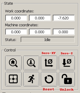
Additionally, the Candle Program provides a graphical interface to the CNC machine, along with providing utility commands, via buttons, for actions like doing a machine “Reset” and “Unlock” if an error occurs, and “Zeroing” either the X-Y axes or the Z-axis, for example.
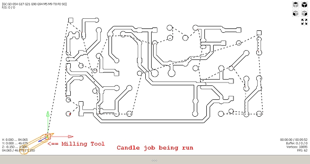
When the CNC machine is being controlled by Candle, a graphical display is active, showing on the computer screen what the CNC machine is being asked to do.
The final element for the control of the CNC machine is an alternative to the computer, called an Offline Controller. As the name implies, when it is being used, the computer (and Candle) isn’t. Within the Offline Controller is another small computer which can provide some of the functionality of Candle, but on a simpler basis. Its basic function is that of a G-Code sender, but it also has the ability to manually move the machine’s axes around and define starting positions. The G-Code information it uses has to be stored on an SD card. This card is then read by the Offline Controller to operate the CNC machine.
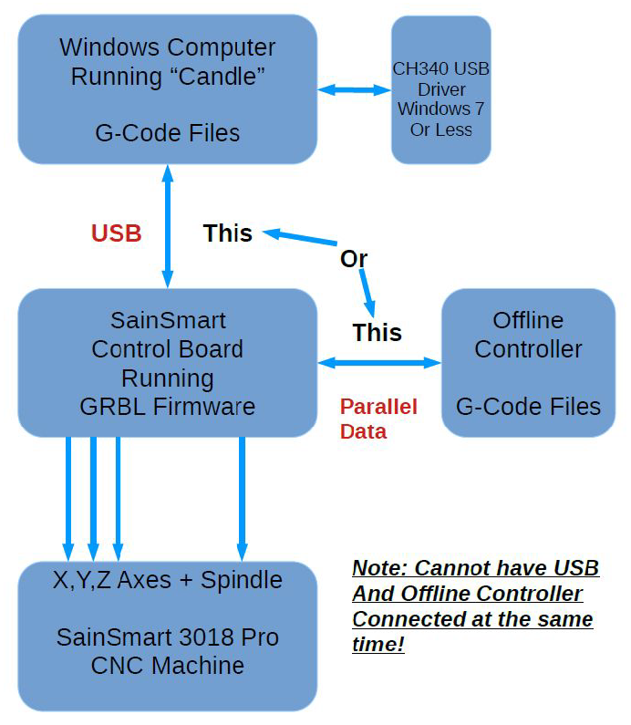
To make all of this discussion more understandable, a pictorial diagram is included, showing the key components available to operate the CNC machine and how they interact with each other. As stated before, none of the software required to create a design is supplied by SainSmart. Various programs, both free and fee based are readily available via the internet to do this work. Their output is always a G-Code file that can be processed using Candle running on a computer or the Offline Controller.
SainSmart 3018 Pro CNC Hardware/Controller/Computer Setup
Making the Wiring Neat
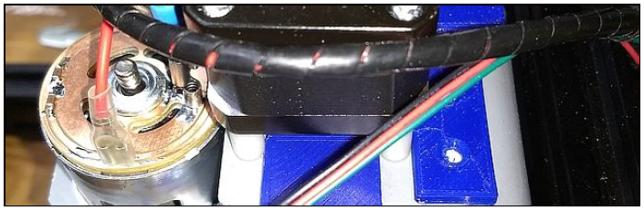
Included with your CNC Machine kit is a 2 meter length of spiral wire wrap, to use in holding the wires together and out of the way of moving parts. Having cut a length to fit the desired run, start the wrap by “flattening out” 1 to 2 turns and put that over the wires needing to be held together. Then, start wrapping the wires using the spiral nature of this material to encapsulate the wires until you reach the end of the run.
Another way of making the wires neat is to use some small “tie wraps’ (not included) available at craft and hardware stores and use those to bundle wire sets together.

Old fashion, black, nylon lacing cord is also an option and is probably the most easy to use. A short length (8-10 inches) can be wrapped around a bundle of wires two times, and then secured with a square knot. The ends are trimmed off with sharp sissors. A few inches away, another “wrap” is placed until the full length of the wire bundle is secured. What makes this method inviting is that any “wrap” can be removed by cutting the knot with scissors and pulling off the lacing cord. Here is a source for Black Nylon Lacing cord.
Basic Machine Tests
Now that you have your CNC machine all assembled and wired, it is time to make sure that it operates correctly. This is the recommended start up order for the system.
- Make sure that the USB cable from the CNC machine is plugged into your
computer, then start the computer.
- Start the Candle program and verify in the status window that no errors are showing. Normally, it will show “Idle” if it has connected to the Controller Board properly. If an “Alarm” error is showing, with your mouse, click the Candle “Reset” then “Unlock” buttons in that order to get to the “Idle” condition.
- Make sure that the 24 volt power supply is connected to the Controller
Board and then to the power mains.
- Turn on the Controller Board by pressing the white “On/Off” button.
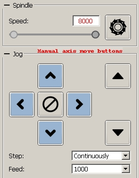
- Next, click on the “Spindle “ button to turn on the spindle motor. Move the slider left and right to verify that the motor speed changes.
- Set the “Feed:” to a value in the 200 to 500 range. With the mouse, click on the left set of direction buttons to verify that the X and Y axes are moving. In a like manner, click on the rightmost up and down buttons to verify that the Z axis is moving.
If all of these tests complete without any issues, you can be assured that your CNC machine is working correctly.
Shutting the machine down uses the reverse of the startup process.
- Turn off the Controller Board.
- Unplug the 24 volt DC supply from the mains.
- Shut down the Candle program.
- Turn off the computer.
Remember, if you run the CNC machine from the Offboard Controller, the USB cable has to be disconnected from the Controller Board.
That completes these assembly notes. We hope they have been helpful. Please send any comments, additions, or corrections your might have to the SainSmart support group: support@sainsmart.com