Adding Axis Limit and Emergency Stop Switches to a SainSmart 3018 Pro CNC Machine
 Updated
Based off of the works of by Jim Kortge
The items you may need:
- SainSmart Genmitsu CNC Router 3018-PRO DIY Kit
- Download the associated files
- Limit switches
- PETG Filament
- 3D Printers
Introduction
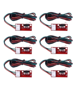
This document contains the design and implementation information to add a set of axis limit switches to the above mentioned CNC machine, along with an implementation of an Emergency Stop switch. (Note: There is not provision for an Emergency Stop Switch on 3.4 control board). The limit switches were purchased from amazon.com and selected because of positive ratings from other buyers. There are 6 switch assemblies in the set along with supplied 3-wire cables to hook them up.
Step 1: Switch Assemblies
In order to mount the limit switches at the required axis locations, a set of 3D printed mounting plates were designed, along with another set of plates to trigger the switches. Those parts are shown below. Switches are affixed to a mounting plate with Casein glue. Before gluing down a switch, clip off the leads on the bottom that extend through the printed circuit board, so they will lie mostly flat on the mounting plate. Each switch is located on an axis to minimize the impact on the available axis travel.
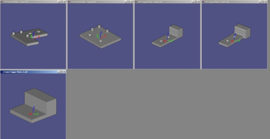
Step 2: Switch Mounting and Trigger Plates
A separate mounting plate/actuator was designed to implement the Emergency Stop. Those mounting plates are also shown below.
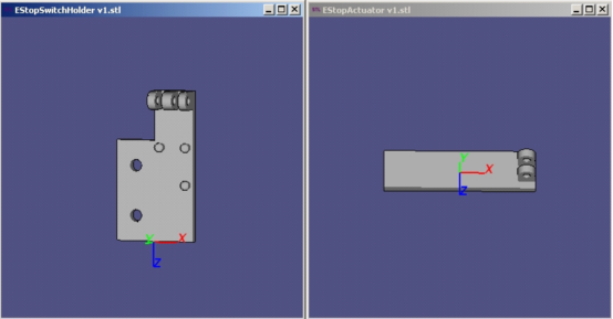
Step 3: EStop Switch parts
These two parts fit together and are held with a 1/8 inch steel pin. The actuator part is movable and is pressed to engage the Emergency Stop function if something goes awry during machining.
Next is a series of photos showing how each set of parts is mounted on the CNC machine.
The first photo, taken from the back, shows the X-axis parts. The switch holder is mounted to the frame rail with 5 mm nylon screws and hammer head nuts. The trigger part is mounted to the motor carriage assembly with double sided tape.
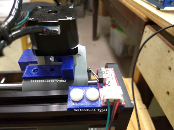
Step 4: X-Axis limit switch implementation
Y-axis limit switch parts are mounted under the machine on the left, horizontal frame rail using 5 mm nylon screws and hammer head nuts. A trigger plate is mounted to the platen with T-nuts and Allen Head cap screws, as suitable nylon screws were not available in my inventory. The next photo shows how these parts were mounted.
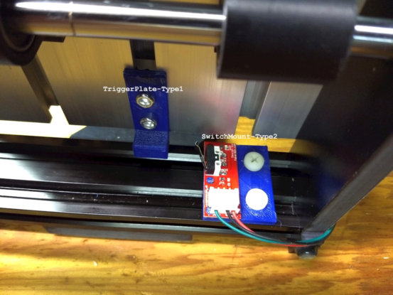
Step 5: Y-axis limit switch implementation
The next photo shows the details of the Z-axis parts and their mounting. The switch holder is affixed to the movable motor assembly with double sided tape, while the trigger plate is attached to the stationary part of the motor assembly with double sided tape. This photo is taken from the right side of the machine.
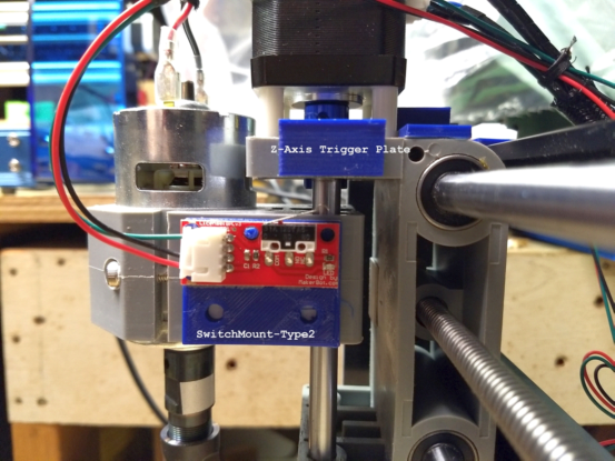
Step 6: Z-axis limit switch implementation
Finally, a photo of the Emergency Stop switch implementation, followed by a close-up of that switch assembly. The wiring was routed into the top channel of the frame and held in place with 6 mm X 4 mm pieces of Ensolite (semi rigid) foam cushioning material. (If I ever find the source of the plastic filler strips that SainSmart used in the PROVer to cover the limit switch wires, I’ll replace the Ensolite with that type.) Notice on the close-up photo that the switch itself has been unsoldered, the leads straightened, and the switch resoldered to the PCB, so that it can be activated by the moving actuator part. The actuator part joint is purposely made stiff enough that the switch is kept activated until the actuator part is manually lifted.
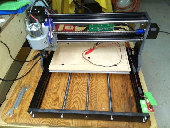
Step 7: Emergency Stop Switch Implementation
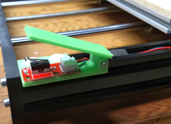
Step 8: Emergency Stop Switch Closeup
One might ask, where does all of that wiring go and how is it connected to the controller board? Well fortunately, the controller board is designed to handle axis limit switches and even an Emergency Stop switch. The wiring itself is mostly common sense. Route it so that it won’t be in the way of the moving platen (where the work piece goes) or the Z-axis motor assembly. I like to tidy up the wiring using zip ties or my preference, old fashioned, waxed nylon lacing cable. Believe it or not, that stuff can still be found at all of the usual places, like Amazon and most electronic outlets!
Step 9: Wire routing
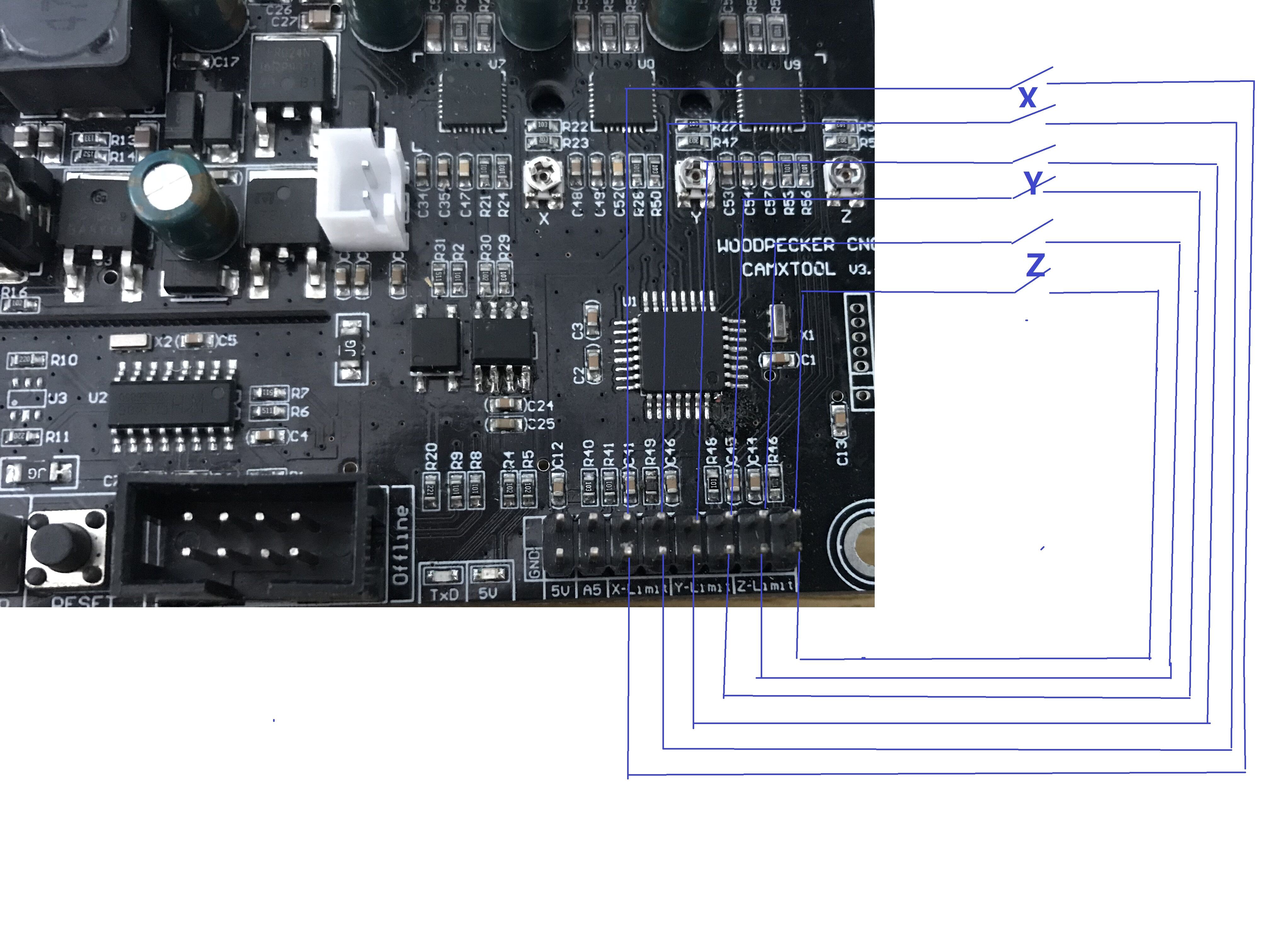
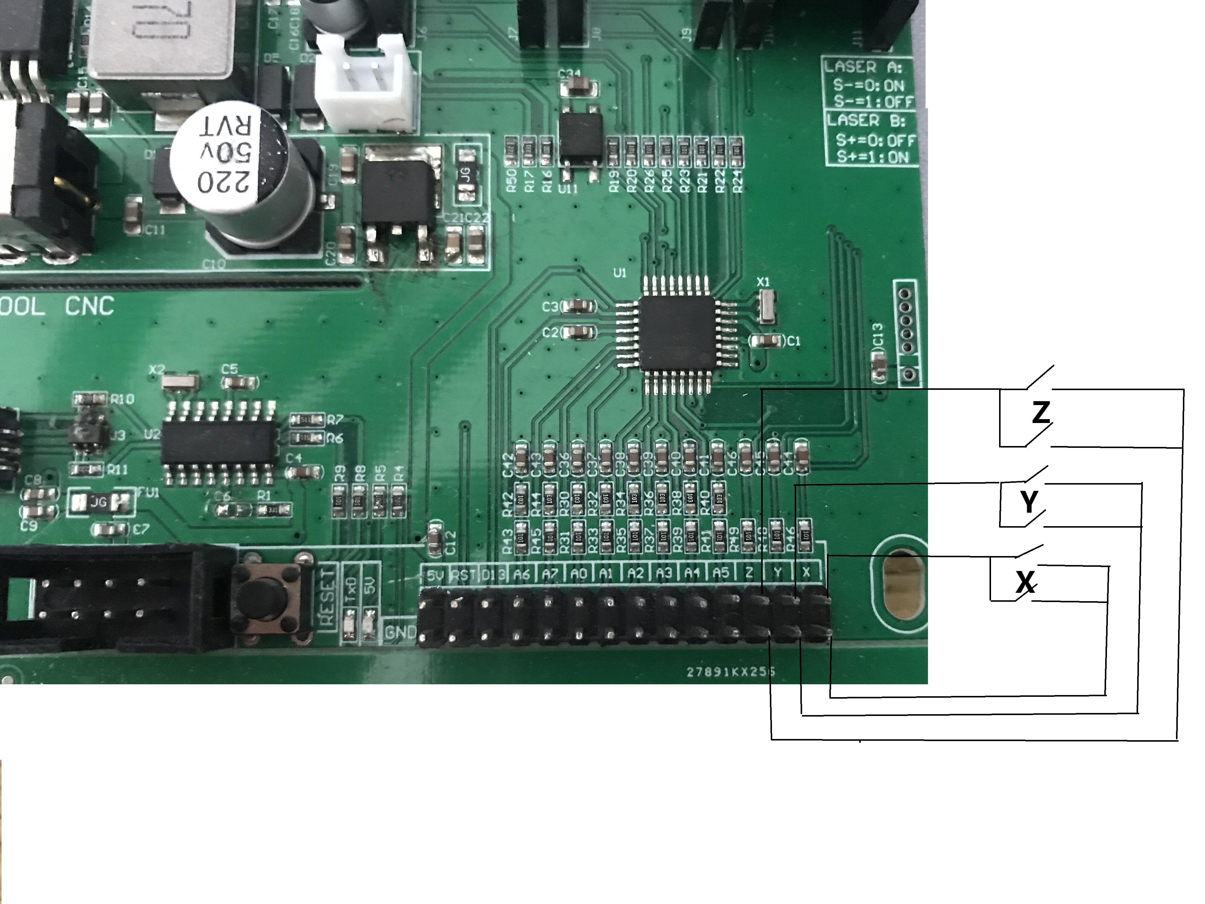
When looking at the back of a typical controller board, there is a pin-header assembly toward the bottom-left. At the right side of this header are the words Xen, Xen, Yen,Yen etc. moving toward the left. This is shown in the next photo.
That’s it. If you have access to a 3D printer, either one you own or have one available at your local library, maker space, or University, you can fabricate the necessary switch mounting parts. Tough PLA or PETG filament is suggested for strength, using 100% fill for all parts. The switch assemblies can be sourced from Amazon and probably others, but I know the Amazon sourced parts work correctly in this implementation.
Have fun upgrading your SainSmart 3018 CNC.