Assemble your PROVerXL 4030

Part 1 - Unboxing
Please make sure all the following parts are included. If you are missing any part or have any questions, please email us at support@sainsmart.com
Click here to go straight to assembly if you are feeling adventurous
Mechanical Parts List
No. | Name | Size/Parameters | Pictures | Qty. |
1 | X-Axis & Spindle Z-Axis Assembly | 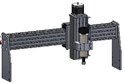 | 1 | |
2 | Y-Axis Base Assembly | 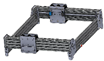 | 1 | |
3 | Spindle |  | 1 | |
4 | Collet |  | 1 | |
5 | Dust Baffle |  | 2 | |
6 | NEMA 23 Stepper Motor |  | 4 | |
7 | Stepper Motor Mount |  | 3 | |
8 | Drag Chain Mount |  | 1 | |
9 | Drag Chain Mount |  | 1 | |
10 | Drag Chain Mount | 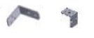 | 2 | |
11 | Cable Management |  | 1 | |
12 | MDF Spoil Board | 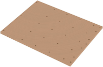 | 1 | |
13 | Bakelite Sheet | 175 x 100 x 5mm | 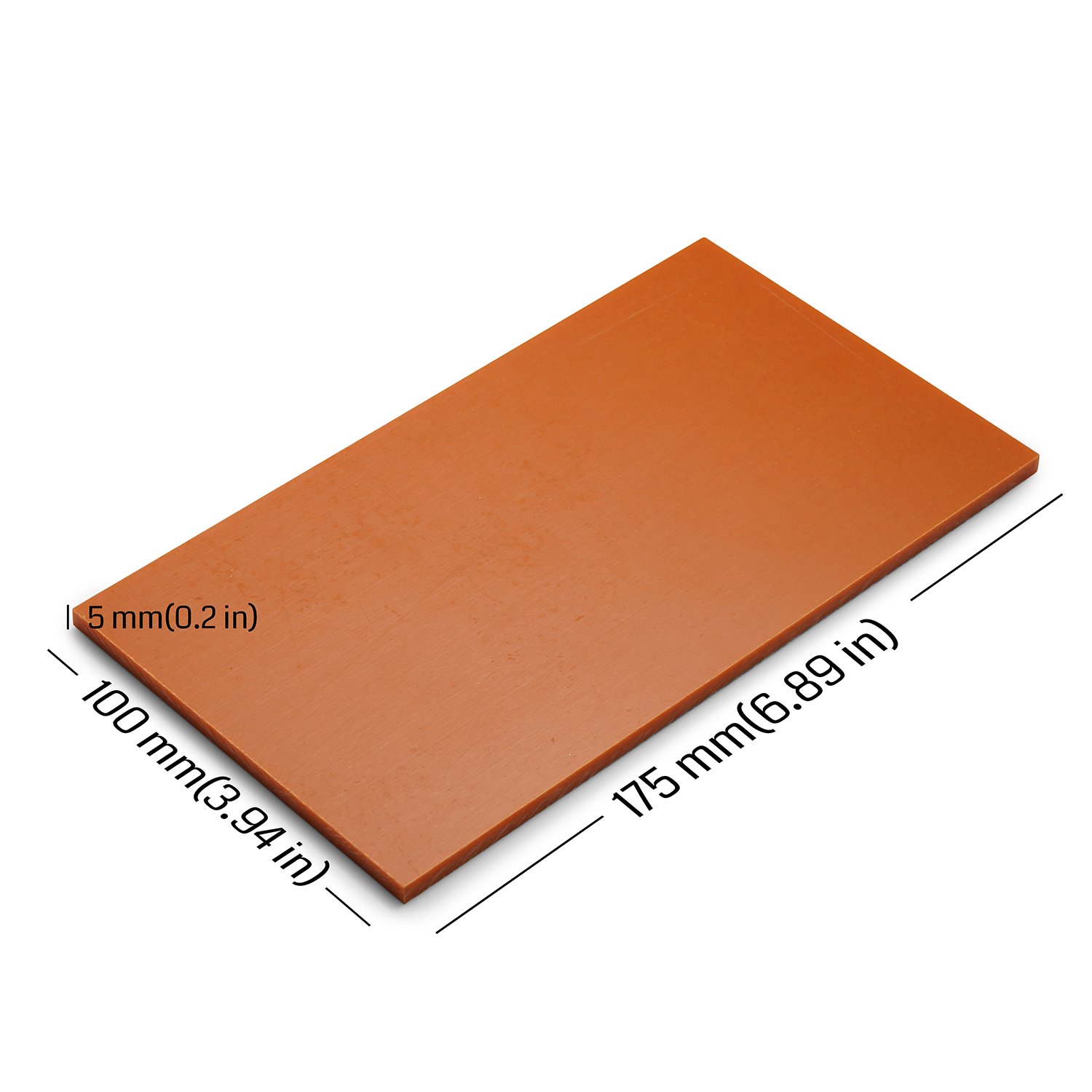 | 1 |
14 | MDF Board | 175 x 100 x 5mm | 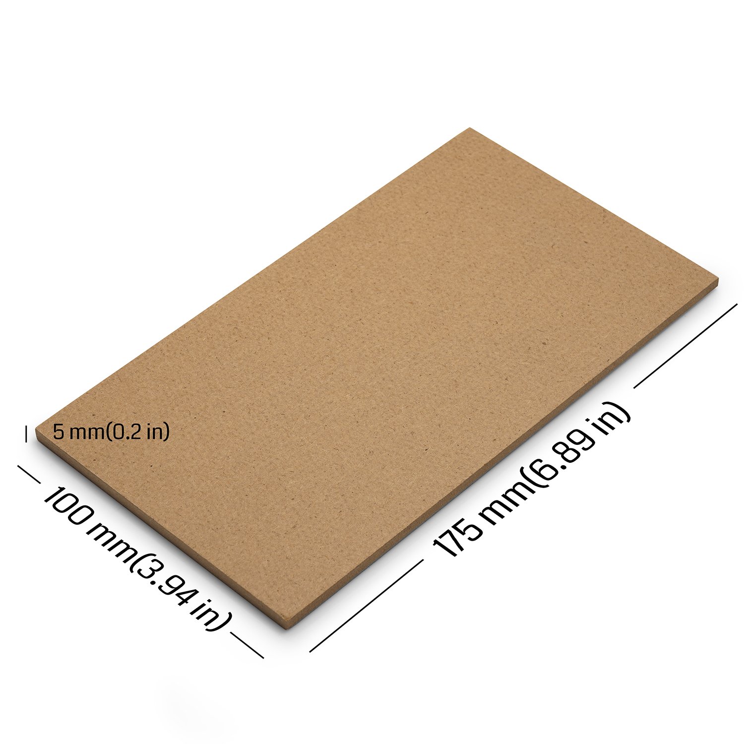 | 1 |
Electrical Parts List
No. | Name | Size/Parameters | Pictures | Qty. |
15 | PROVerXL Control Center |  | 1 | |
16 | USB cable | A-B | 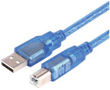 | 1 |
17 | Power cable (US) | 1.2M |  | 1 |
Tools/Accessories Parts List
No. | Name | Size/Parameters | Pictures | Qty. |
18 | Set of Clamps | Material Clamps |  | 1 |
19 | Probe | Z-Height Mapping Probe | 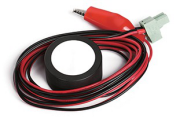 | 1 |
20 | Engraving Bit | 20 Degree, 0.2mm Cutting area, 3.175 Diameter | 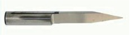 | 10 |
21 | Nano Blue Coat Bits | 3.175mm Shank, Cutting Edge Diameter: 0.8-3.0mm | 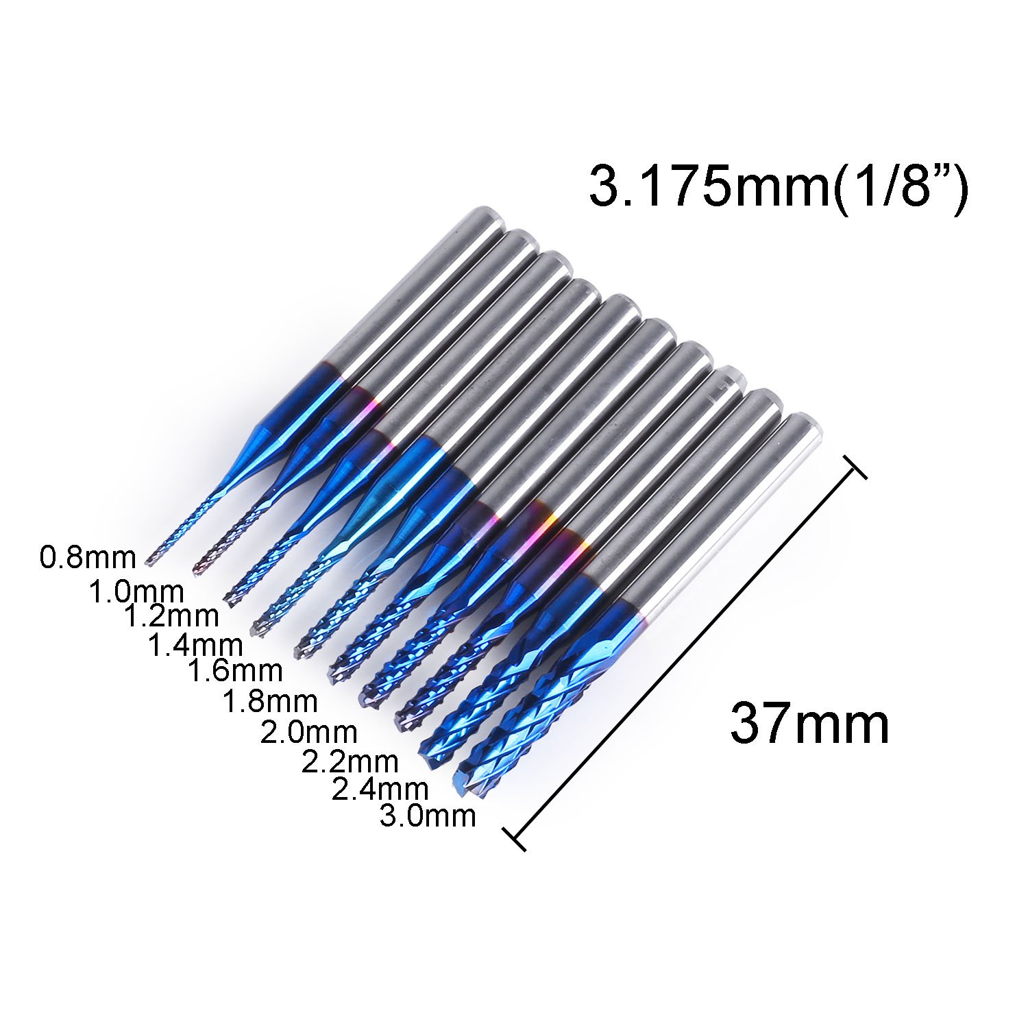 | 10 |
22 | Allen Wrench | 2.0mm, 2.5mm, 3.0mm, 4.0mm, 5.0mm | 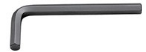 | 4 |
23 | Wrench |  | 1 | |
24 | Nylon Braided Wrap | 340mm |  | 1 |
25 | User Manual |  | 1 | |
26 | USB Stick |  | 1 |
Screws/Other Parts List
NO. | Name | Pictures | Qty. |
27 | M5 T-Nut | 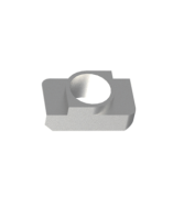 | 2 |
28 | M5 x 8mm Socket Cap Screw |  | 4 |
29 | M5 x 16mm Socket Cap Screw |  | 14 |
30 | M5 x 20mm Socket Cap Screw |  | 6 |
31 | M5 x 50mm Socket Cap Screw |  | 8 |
32 | M5 x 55mm Socket Cap Screw |  | 4 |
33 | M4 x 6mm Socket Cap Screw |  | 2 |
34 | M4 x 8mm Socket Cap Screw |  | 2 |
35 | Coupler |  | 3 |
36 | 5mm Spring Washer |  | 10 |
37 | 5mm Flat Washer |  | 10 |
Part 2 - Mechanical installation
2.1 Preparing your base assembly
What you will need
- PROVerXL Base Assembly
- (8) M5 x 50mm Socket Cap Screw
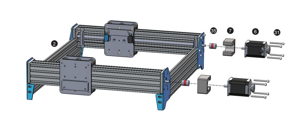
- (2) Stepper Motor Mounts
- (2) Flexible Couplers
- Allen Wrench
Step 1: Inspect your Base Assembly after removing it from the packaging. Before starting assembly, verify the base is square by using a 90-degree straight edge, as shipping may have caused things to shift.
Step 2: Install the flexible coupler onto each Y-Axis leadscrew. Loosen the small set screw to ensure the Lead screw will completely seat inside.
Step 3: Tighten (2) M6 x 16mm screws to secure the lead screw mount.
Step 4: Next comes the Motor Mounts & Stepper Motor. Lay the Stepper Mount on your flat surface, positioning it so the open side will not face down when installed. Place the NEMA-23 Motor onto the mount aligning the screw holes. Insert the M5 x 50mm screws.
Step 5: Holding the Mount & Motor together with the screws, install the assembly to base as shown in the diagram.
2.2 Finishing your base assembly
What you will need
- PROVerXL Base
- (6) M5 x 20mm Socket Cap Screws
- (4) M5 x 16mm Socket Cap Screws
- MDF Spoilboard
- (2) Dust Baffles
- (6) Wire Holder
- Allen Wrench
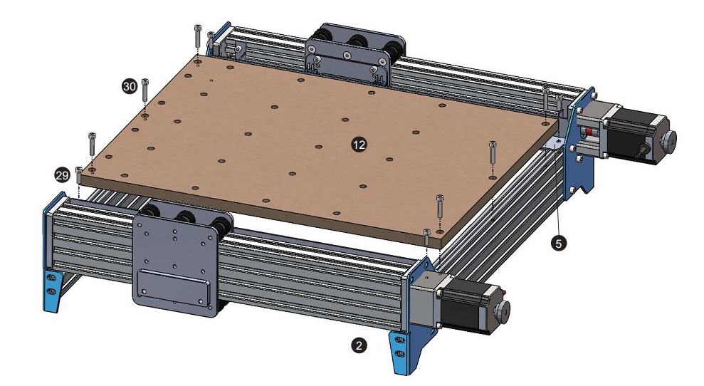
Step 1: Position the MDF Spoilboard on the PROVerXL Base and align each Dust Baffle to the side of the spoilboard. Align with the screw holes and tighten down with the M5 x 16mm screws.
Step 2: Align the MDF Spoilboard with the screw holes at the front and back of the machine. Be sure the board is right side up (Threaded Inserts should be towards the bottom. If you install it in reverse the mounting screws will protrude from the top of the spoil board). Tighten with M5 x 20mm Screws.
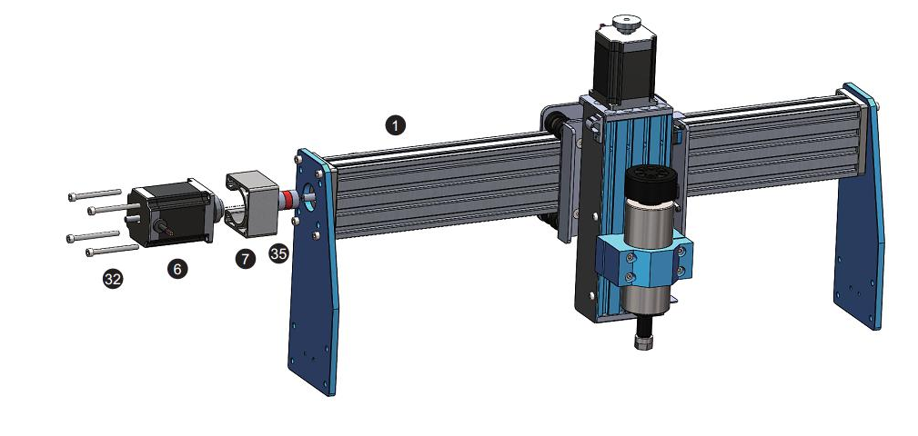
2.3 Preparing your X-Axis Gantry
What you will need
- X-Axis Gantry
- Flexible Coupler
- Stepper Motor Mount
- NEMA-23 Stepper Motor
- (4) M5 x 55mm Socket Cap Screws
Step 1: Install the flexible coupler to the X-Axis Leadscrew. Be sure to loosen the grub screws to ensure the shaft fully seats inside.
Step 2: Just like the Base preparation. Prep your Stepper Motor Mount + NEMA 23 Motor and 4 socket cap screws and remember to position the mount with the opening facing towards the rear of the gantry.
Step 3: Mount the assembly to the X-Axis. Tighten the grub screws on the coupler. Manually twist the wheel on the Stepper motor to ensure smooth movement of the Gantry on the X-Axis.
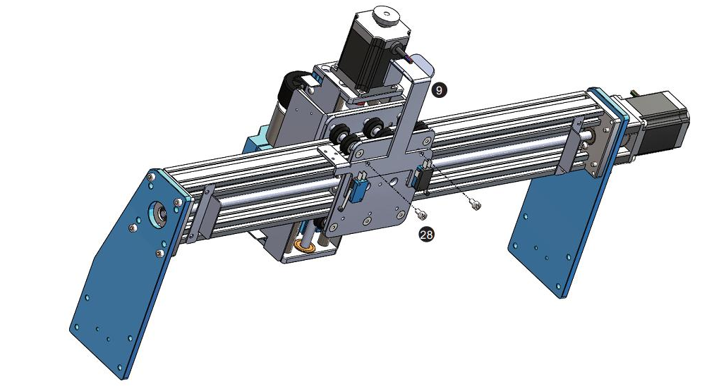
2.4 Finishing your X-Axis Gantry
What you will need
- X-Axis Gantry
- X-Axis Limiter + Drag chain guide
- (2) M5 x 8mm Socket Cap Screws
- Allen Wrench
Step 1: Position the X-Axis Limiter to the rear of the Spindle Carriage as shown in the diagram. Install the bracket and tighten the screws.
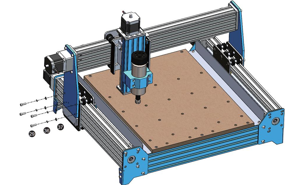
2.5 Finishing frame assembly
What you will need
- PROVerXL Base
- X-Axis Gantry
- (8) 5mm Spring Washers
- (8) 5mm Washers
- (8) M5 x 16mm Socket Cap Screws
- Allen Wrench
Step 1: Position the X-Axis gantry onto the Y-Axis carriage mounts as shown in the diagram. Each carriage has an acrylic plate that will hold the gantry at the appropriate height. Install the gantry using a 5mm washer, 5mm spring washer then M5 x 16mm screw as shown in the diagram.
Step 2: Secure the opposite side to complete the installation.
Step 3: Rotate both wheels on your Y-Axis stepper motors to ensure smooth movement of the X-Axis Gantry along the Y-Axis.
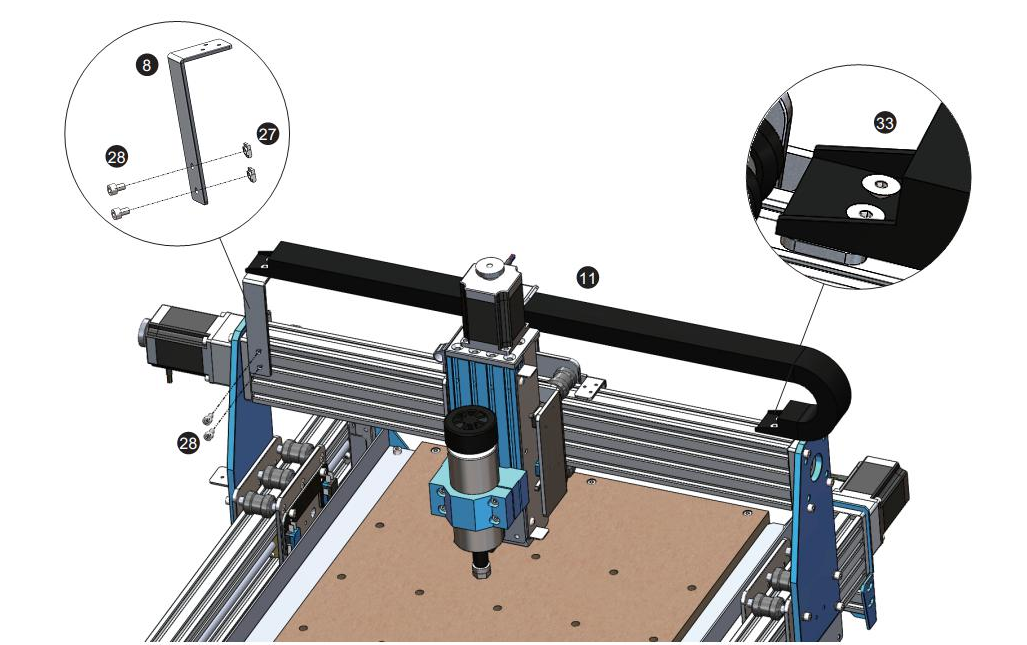
2.6 Installing the X-Axis Drag Chain
What you will need
- PROVer XL frame
- Drag Chain
- X-Axis Drag chain mounting bracket
- (2) M5 x 8mm Socket Cap Screws
- (2) M5 T-slot nuts
- (5) M4 x 6mm Screws
- Allen Wrench
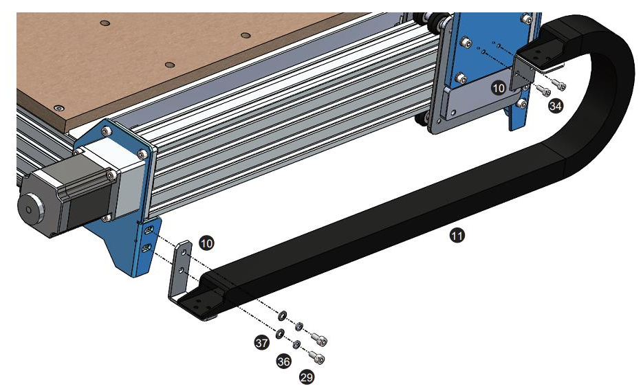
Step 1: Per the diagram you will install the X-Axis drag chain mount. Align the T-Slot nuts with the bracket (the screws and nuts will be positioned on the top 2 channels of the C-Beam). Secure the bracket with the screws.
Step 2: Position the Drag chain as shown in the diagram. Start with securing the side closest to the Spindle Gantry and secure with (3) M4 x 6mm screws.
Step 3: Run the Drag Chain underneath the X-Axis limiter as shown in the diagram and secure the Drag chain mount with your M4 x 6mm screws.
2.7 Installing the Y-Axis Drag Chain
What you will need
- Y-Axis Drag Chain
- Y-Axis Drag Chain Mounts
- (2) M4 x 8mm Socket Cap Screws
- (2) M6 x 10mm Socket Cap Screws
- (6) M4 x 6mm Screws
- Allen Wrench
Step 1: Position the narrow drag chain mount to the rear of the machine as shown in the diagram. Attach the bracket with (2) M6 x 10mm socket cap screws.
Step 2: Install the bracket to the carriage as shown in the diagram using (2) M4 x 8mm socket cap screws.
Step 3: Position the drag chain per the diagram using (6) M4 x 6mm screws. (The side with the Compression DIN Connector for the spindle goes to the Control Box). While mounting the drag chain take care not to damage any of the cables or connectors.
Congratulations! Now your PROVerXL machine body is fully assembled!
Now let's move onto wiring
Part 3 - Wiring
3.1 Wiring Your Electronics
What you will need
- PROVerXL
- PROVerXL Control Center
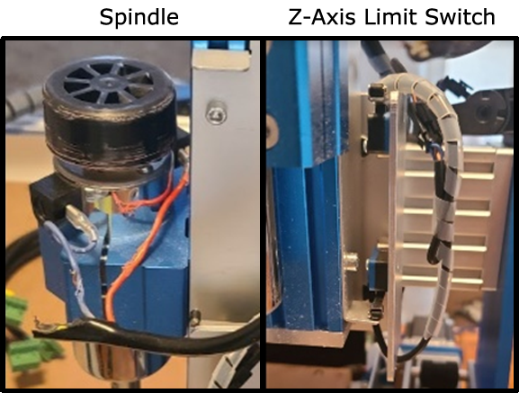
Step 1: Start with the Spindle and X-Z Carriage it is mounted on. Using the labeled cable connectors you need to connect the Z-Axis Limit Switches to the Cable whip and wire the Spindle (there is no requirement for which color goes onto which side of the spindle).
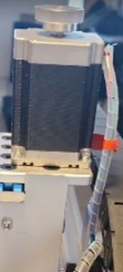
Step 2: Connect your Z-Axis Stepper motor
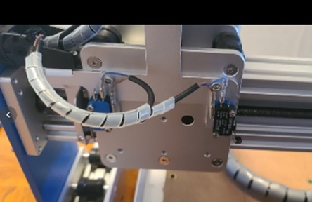
Step 3: Connect your X-Axis limit switches
Step 4: Wire the Y-Axis Stepper Motors. Find the longer Y-Axis Motor cable (Y2) and run that to the left side while reserving the shorter cable marked X for the X-Axis Motor and finally the medium length cable (Y1) for the right-side Y-Axis motor.
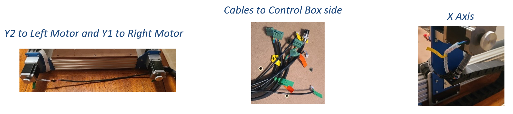
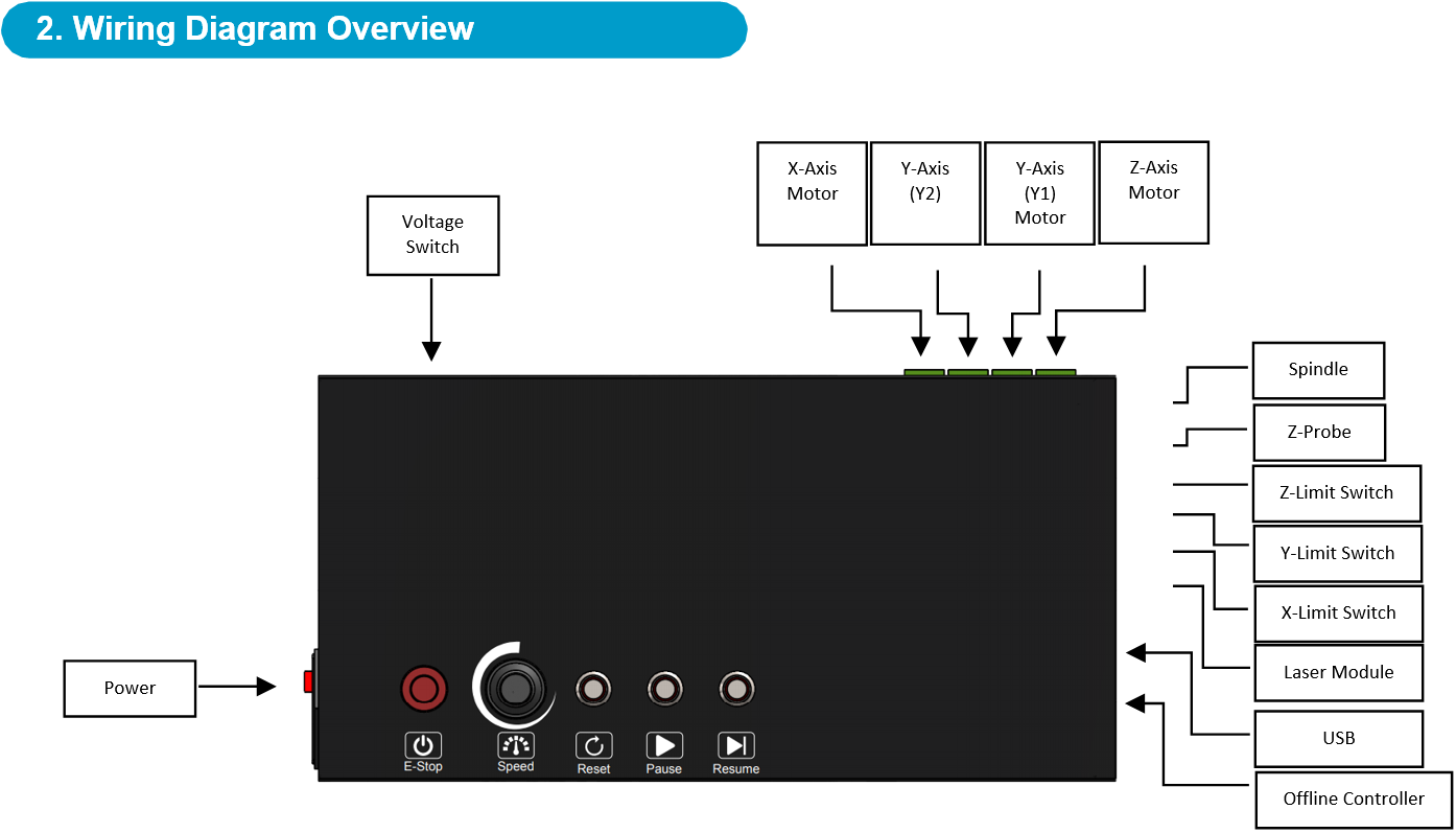
Step 5: Follow the Wiring Diagram Below in order to connect all the wires from the Cable Whip (Looks like central image above)