LightBurn Quick-Start Guide

The items you may need:
Step 1: Connecting Your Laser
Before you go any further, start off by having your CNC (with installed laser module) powered up and connected via USB to your computer. With that done, start up LightBurn and either start a trial or enter your product key you received after purchase.
From there you will see a Device Discovery Wizard pop up as seen on the right which will automatically detect your machine and provide some information in regards to the work area and Com port; make sure to take note of the latter for your use further into this guide.
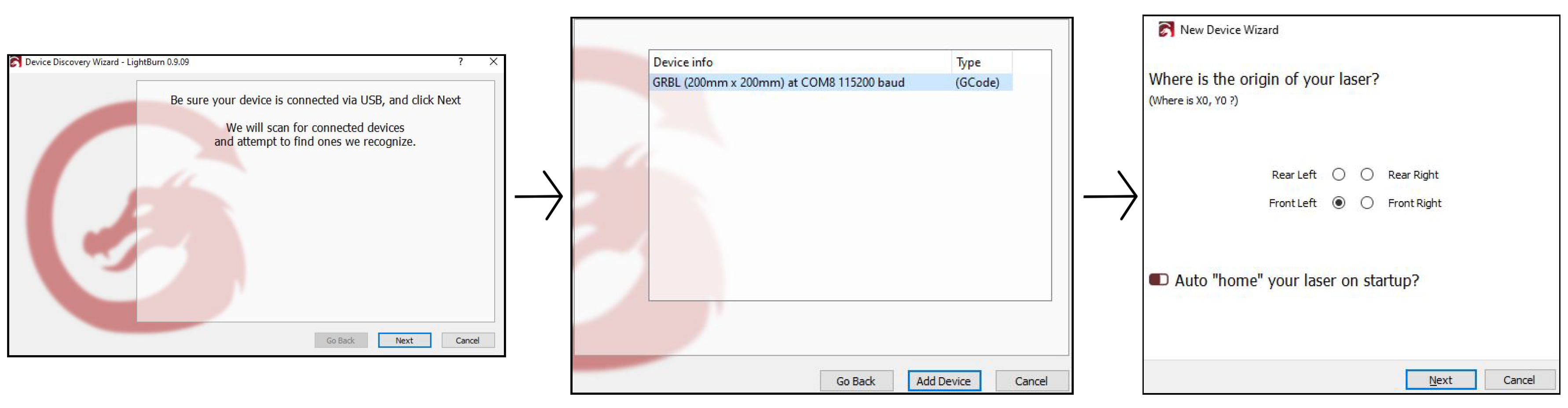
The third and final page shown above of the New Device Wizard is especially important to take notice of, because it must be set differently for 3018 Pro & PROVer machines:
- 3018 Pro: For users of this machine, you don’t have endstop sensors, so you cannot home your machine and set X and Y to 0. As such it does not matter which position you select, only that you turn Auto Home off.
- PROVer: This machine does have end-stops/limit switches, so set the origin to whatever corner it homes to, and keep Auto Home enabled. While not fully utilized by this guide, this is a great feature as you learn more about your machine and it’s capabilities.
Finish the Wizard and now at the software’s main page, look to the bottom right of your screen for the menu to the right. Select the noted com port from earlier.

Step 2: Preparing Your Project
LightBurn is a very versatile program with a lot of depth, and it’s important to note as you follow this guide that there are a number of ways to do what will be shown in different ways, each for different situations.
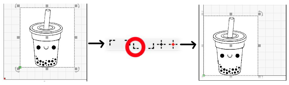
To start off, you need to bring your project into LightBurn. In this case a black and white image was selected for engraving, and a blue rectangle vector not shown to the left which will be used to cut the engraving out.
Steps Taken:
1. Open up the file you want to work with and you should see it represented in the work area. With the Image/File selected, look in your toolbar towards the right-hand side and find the “L” shaped bracket (Seen circled in red below.
- What this does (also shown below) is automatically place your image perfectly in the bottom left corner.
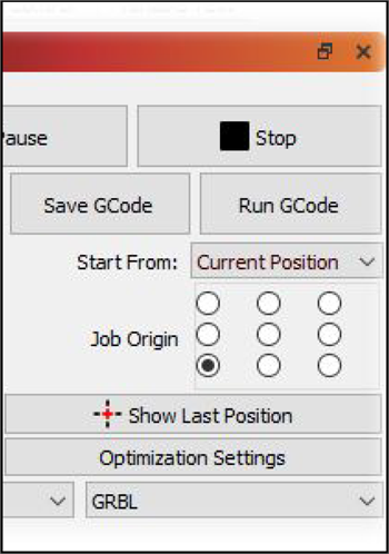
2. For ease of use, set the Job Origin to the bottom-left position, and set “Start From:” to Current Position. Jointly, what this and the prior step do is arrange it so that wherever you have your laser position at when you hit play, is where the bottom left corner of your project will be. This a great quick-and-dirty way to do projects with minimal setup time.
- One limitation to this method, is that it is up to the user to know that they have enough room for movement on the X/Y axis for every part of your project to be reached.
3. Go to the command tab, type “$32=1” and hit enter; this will set your machine into Laser Mode. Be sure to Type in “32=0” when you are done. This will return it to CNC mode, which you must do before using the machine as a CNC again. Next go to Device settings in Lightburn and set S-Value Max to be equal to your maximum spindle speed ($30). For most dedicated laser engravers this value will be 1000, while for most CNC's this will be set to 10000
4. Fasten the material you will be working with on the bed, and use the arrows on the movement tab in LightBurn, move the laser in to place. To assist yourself in positioning, you can set your laser to fire at 0.0% to have it running while you find the corner of your materials. Not that this feature might have to be enabled in your software settings.
5. Keeping the laser firing at 0.35% and raise/lower the Z axis until your laser is in focus. Once done, deactivate your laser.
6. With this next step you need to assign power/speed settings to each layer. As seen in the image below, the imported JPG has one setting and the blue vector that was added has another. Assigning different colors to different aspects of a project opens up a lot of flexibility for users to create a variety of effects.
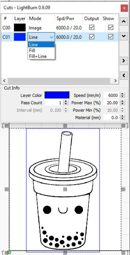
7. The last step before you tell your machine to get started is to consider the Mode settings for each layer. For our first layer, the image, there are no options, but for vectors like the 2nd layers, you have the option to tell the machine to perform a few different tasks:
- Line Mode: This mode makes the laser trace the line and nothing more. This would be the setting to use if you want to cut your project out of a larger piece or engrave thin, precise lines.
- Fill Mode: Much as the name implies, this mode fills any closed areas of a layer. For example in the image to the right, it would fill the entire area inside of the blue lines, but if there was a line sitting by itself it would not work.
- Fill + Line: It’s exactly as the name implies this time. The reason you might want to use this mode is that the Fill mode by itself does not actually cover the line itself, so the rectangle would be ever so slightly undersized compared to this mode.
8. You’re good to go! Press the play button and don’t forget to put on your protective eye-wear. Always make sure to stay with your machine for the entire operation in case of fire or some other malfunction.