Troubleshooting For Common Issues with 3018-MX3

Problem: The X Axis is Binding/ Not Moving Smoothly
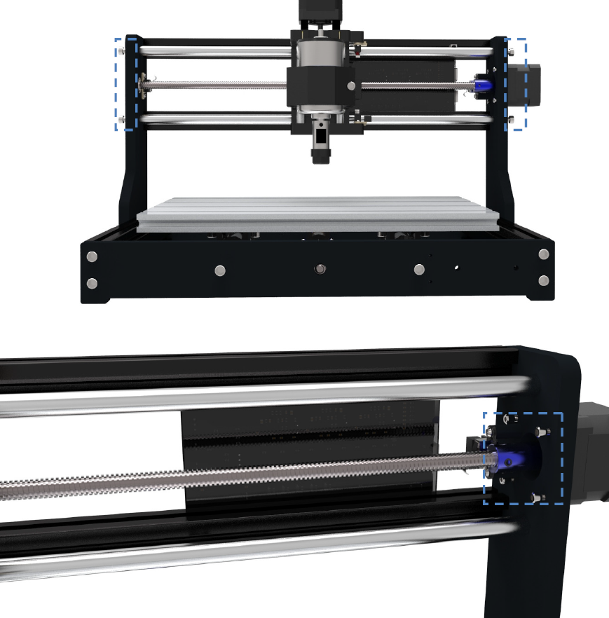
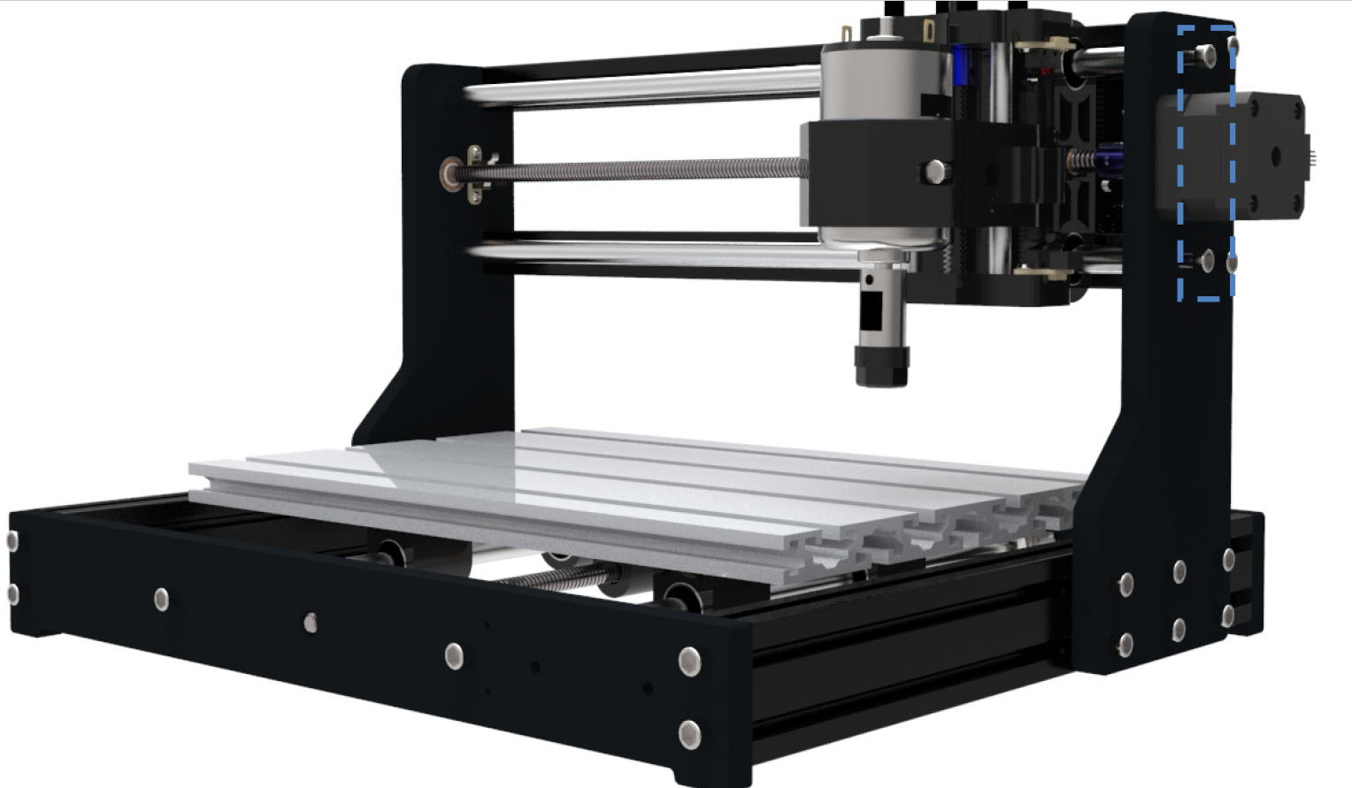
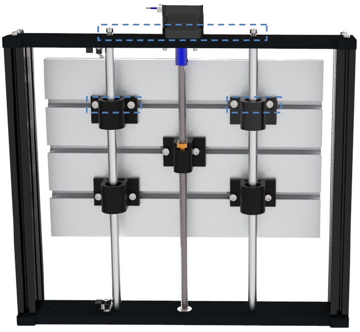
- As shown below, loosen four screws of the two Guide Rails (X-axis),and also loosen these four screws of Stepper motor
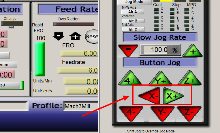
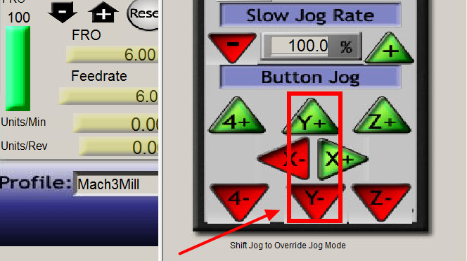
- Power on the CNC, open up Mach3 and use the buttons shown below below to control the CNC for the next steps.
- Bring the spindle all the way to the left hand side of the CNC, stopping just short of colliding with the side. With that in place, tighten up the two screws that connect to the linear guide rails shown below:
- With those screws tightened, use Mach3 to move the spindle all the way to the opposite side, stopping once again just before it runs into the side. and tighten the screws shown which are connected to the linear guide rails.
- Taking into account the adjustment you have made, now use Mach3 in order to move the spindle from side to side and see if the issue has resolved itself. Assuming that it has, tighten up the 4 screws on the X axis stepper motor.
Y Axis is Binding/Not Moving Smoothly
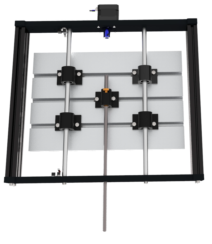
- As shown below, loosen four screws of the two Guide Rails (Y-axis),and also loosen these four screws of Stepper motor.
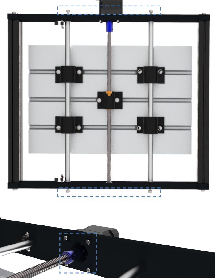
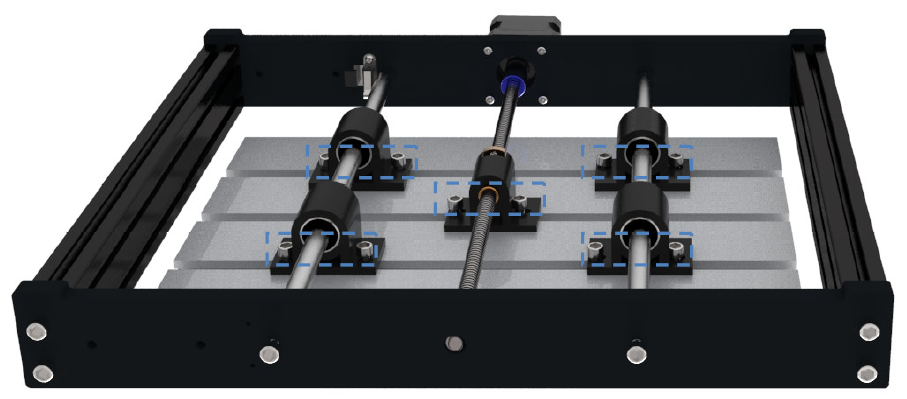
- Loosen the screws that attach all the bearings mounts to the CNC bed
- Power on the CNC, open up Mach3 and use the buttons shown below below to control the CNC for the next steps.
- Next, move the Y axis/bed towards the front of the CNC. The further it is without colliding with the frame, the better. With this done, tighten the two front screws connecting to the guide rails, as well as the two front-most bearing mounts.
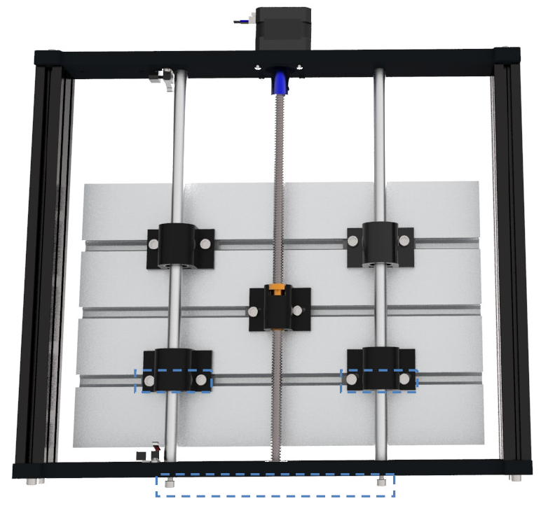
- Now bring the bed/Y axis as far back towards the stepper motor as possible, making sure not to collide with the frame, and now tighten the remaining linear rail screws, as well as any loose bearings mount screws.
- Move the Bed/Y axis back and forth a few times and see how it runs. Assuming all is well, Move the bed all the way back and tighten up the stepper motor mount screws.
X Axis Lead Screw Wobbles/Is Crooked
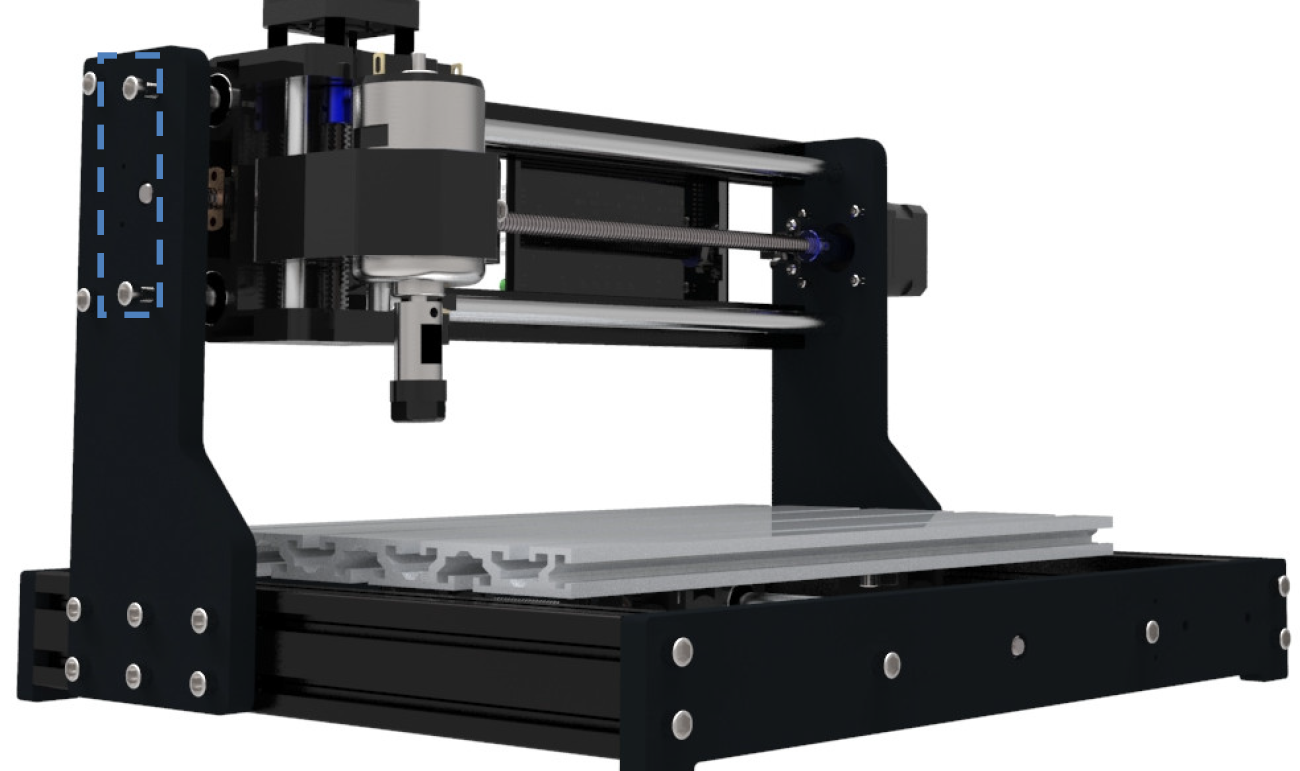
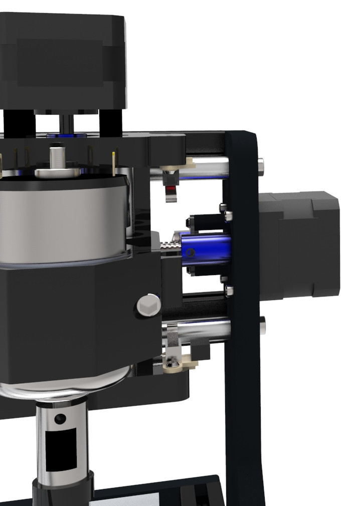
- Loosen the screws anchoring the X Axis stepper motor to the side of the CNC.
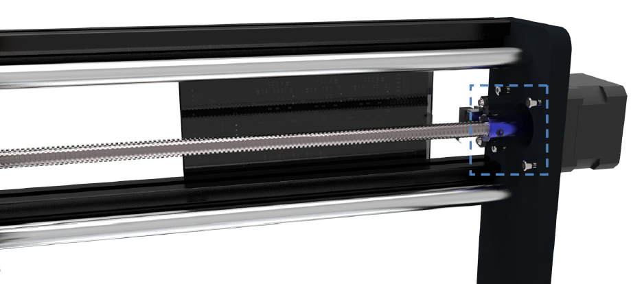
- Power on your CNC, open Mach3 and use the directional arrow button to bring the spindle near the coupler which connects the lead screw to the stepper motor.
- Loosen the set screws on the coupler, which used to fix the lead screw(X axis).
- With both set screws loosened, take turns tightening a tiny bit while alternating between each set screw, taking care that in the end they are about equally screwed in. This is done to avoid the lead screw wiggling.
- With the coupler securely in place, now tighten the screws that anchor the stepper motor to the frame. With everything back in place test and repeat the process until the wobble is eliminated.
Y Axis Lead Screw Wobbles/Is Crooked
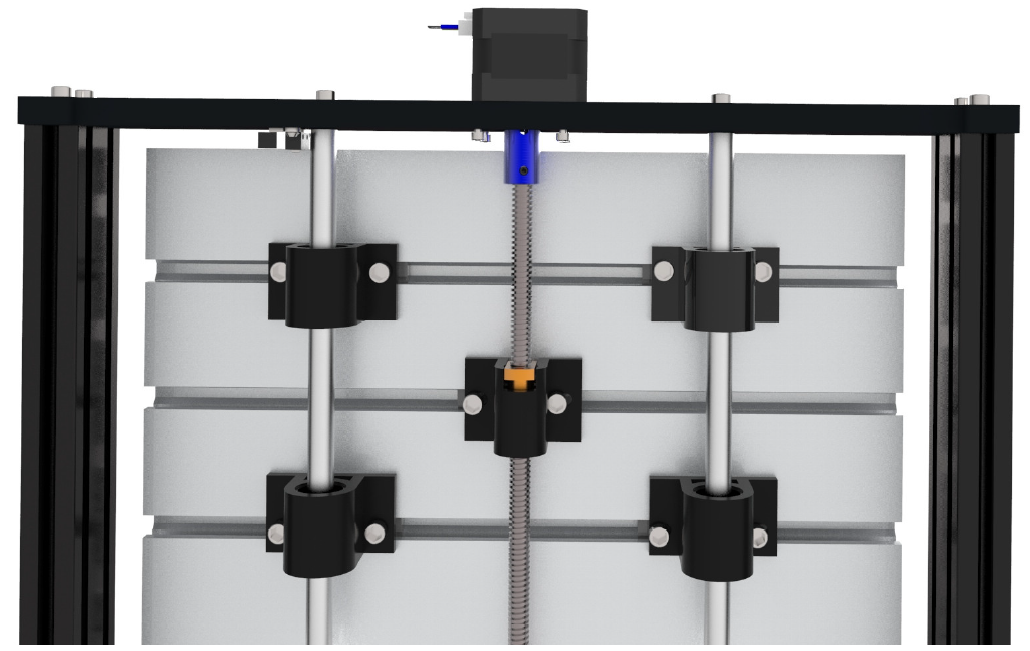
- Loosen the four set screws anchoring your stepper motor to the CNC frame.
- Power on your CNC, open Mach3 and use the directional arrow button to bring the CNC bed/Y Axis near the coupler which connects the lead screw to the stepper motor.
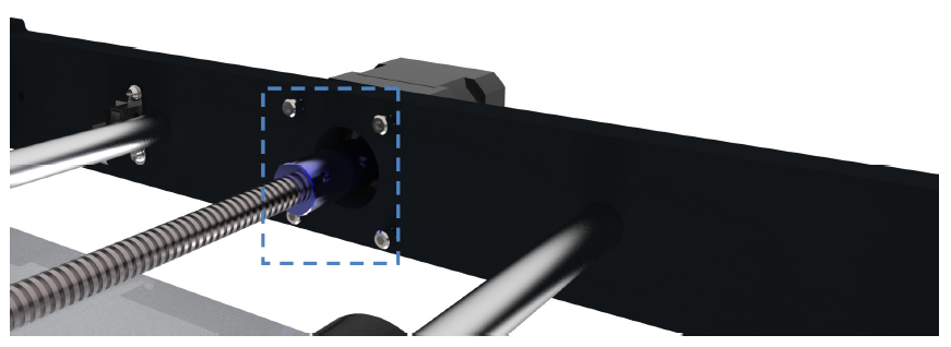
- Loosen these two screws on the coupling, which used to fix the lead screw(Y axis).
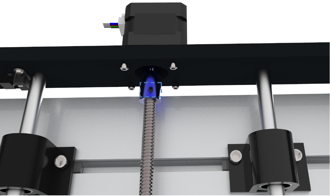
- With both set screws loosened, take turns tightening a tiny bit while alternating between each set screw, taking care that in the end they are about equally screwed in. This is done to avoid the lead screw wiggling.
- With the coupler securely in place, now tighten the screws that anchor the stepper motor to the frame. With everything back in place test and repeat the process until the wobble is eliminated.
The Threaded Brass Insert Causes a Grinding Noise on the X or Y axis
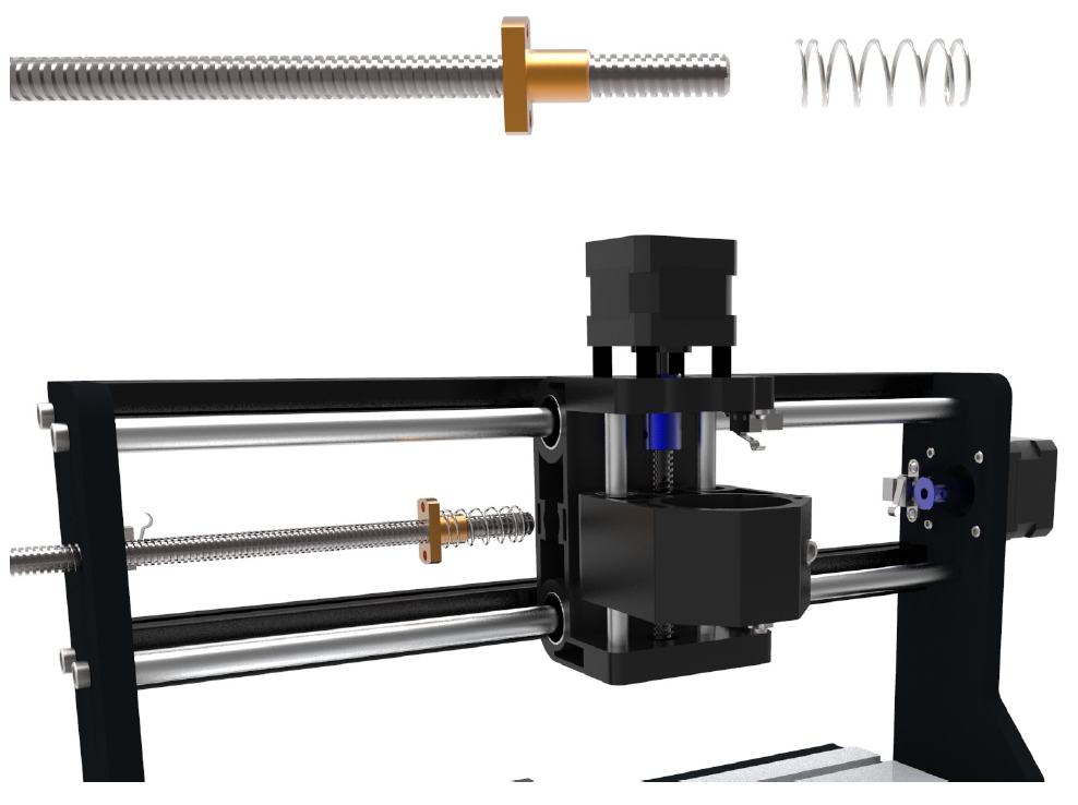
- Detach the lead screw from the couplers by loosening the two set-screws on the coupler. Without these holding onto the lead screw you can pull the it out along with the spring and brass insert.
X Axis
Y Axis
- Fully uninstall the lead screw, as well as separate the spring and brass insert
- Take the lead screw and find the flattest surface possible, such as the bed of a table saw, or a granite kitchen counter. Using one hand, rotate the lead screw on the flat surface while looking at it from eye level to see if there are any noticeable gaps between the threading on the rod and the flat surface. If there is, this could mean that your lead screw is bent or damaged and needs replacement; reach out to us at support@sainsmart.com for further assistance.
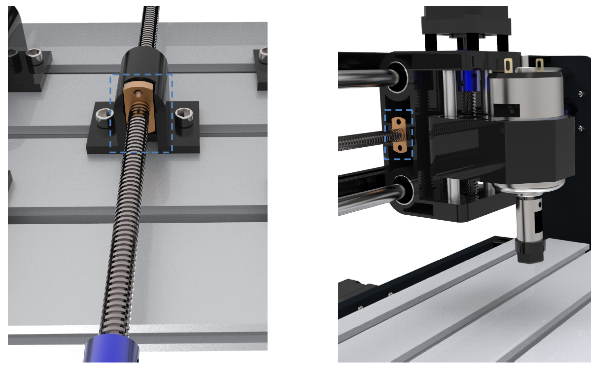
- Take the threaded brass insert and inspect the internal threading for tearing or damage. If there is damage, reach out to us at support@sainsmart.com for further assistance.
- Assuming there was no damaged parts, reassemble everything and reinstall. Take care to adjust the distance between the brass insert so that, after installation is complete, the front of the brass insert is flush with the outer edge of the plastic holder it goes into.
- For good measure, lubricate the lead screws and guide rails for each axis. This will reduce running noise and extends the lifespan of your CNC.