Introduction to CNC for a Total Novice: Tuning GRBL Settings
 Updated
Based off of the works of by Graham Bland
The items you may need:
- SainSmart Genmitsu CNC Router 3018-PRO DIY Kit
- SainSmart Genmitsu CNC Router 3018-PROVer Kit
- Download the associated files
Introduction
This guide is a part of the "Introduction to CNC for a Total Novice"series. Along with the guide itself, to utilize this resource successfully you will need the accompanying files, which you can download together as a .zip file. The files included are as follows:
Files Name | Description |
TracingTest GCode-V2.xlsx | Excel spreadsheet which generates simple GCode used for testing the settings, mainly the acceleration test is relevant here. |
AccelTest.nc | Sample GCode file for the acceleration tests |
1sainsmart.nc | Sample GCode file to engrave‘sainsmart' used with a max spindle speed of 1000 |
1sainsmart8000.nc | Sample GCode file to engrave‘sainsmart' modified for a max spindle speed of 8000 |
dragon.nc | Sample GCode file of a dragon engraving with a max spindle speed of 1000. |
Dragon8000.nc | Sample GCode file of a dragon engraving with a max spindle speed of 8000 |
LaserAccelerationTest-30.nc | Draws a more complex shape designed to determine the effect of increasing the $120-122 acceleration values when using a laser. Acceleration values set to 30mm/sec/sec |
LaserAccelerationTest-1000.nc | As above but with acceleration set to 1000mm/sec/sec |
LaserAccelerationTest-5000.nc | As above but with acceleration set to 5000mm/sec/sec |
SpindleAccelerationTest-30.nc | Draws a more complex shape designed to determine the effect of increasing the $120-122 acceleration values when using a Spindle Motor. Acceleration values set to 30mm/sec/sec |
SpindleAccelerationTest-1000.nc | As above but with acceleration set to 1000mm/sec/sec |
SpindleAccelerationTest-5000.nc | As above but with acceleration set to 5000mm/sec/sec |
What this Covers
At the end of the GRBL configuration page it says the following:
Finally, tune your settings to get close to your desired or max performance. Start by ensuring your $100,$101, and $102 axes step/mm settings are correct for your setup. This is dependent on your stepper increments, micro steps on your driver, and mechanical parameters. There are multiple resources online to show you how to compute this for your particular machine, if your machine manufacturer has not supplied this for you. Tweak your $12x acceleration and $11x max rate settings to improve performance. Set to no greater than 80% of absolute max to account for inertia, cutting forces, and motor torque reductions with speed. Set your $13x max travel settings if you plan on using homing or soft limits. It's recommended to enter something approximately close to actual travel now to avoid problems in the future.
$100-2 have already been covered in‘Introduction to CNC for a Total Novice - Getting Started’ along with some other settings, so this guide will focus on acceleration and max rate settings. Also included is a spindle speed section and some other tips and tricks.
NOTE: the acceleration settings section is duplicated in ‘Introduction to CNC for a Total Novice – Setting up a Laser.’ It is included again here just to emphasize how much of a difference it makes.
Why Should You Bother?
For those with a laser, you might notice that the ends of any line were burnt more than the middle, and for those new to using lasers they might think that this is normal, but this cannot be farther from the truth. Taking the time to really dial in your machine is rewarding in the end results, as well as educational for the user to better understand their machines.
Continuing with the example above, the issue comes down to acceleration settings in the laser, specifically the $12x acceleration parameters. Once you try out different settings, you will find out that, apart from much cleaner lines, the time taken to run a job was greatly reduced, by around 30% in some cases.
The router motherboard was probably not made for a specific router, instead it is programmed for the best adaptability for any number of platforms. We at SainSmart do configure some of the settings for our CNC’s, but there is always room for improvement. Getting them right makes things work much faster without any unwanted side effects.
Viewing & Changing Your Settings
Load Candle (other software is available, but Candle is recommended) on your computer and connect to your router. Once in the software, locate the Console Command box and type “$$” (Without quotation marks, of course) to the router, this will return a series of $x=y lines where x is the parameter number and y is the current value. To change a setting, send a command of $x=y to the router, this will change the setting and store it until you specifically change it again. For example to turn Laser Mode off send “$32=0" .
It is strongly suggested that before you start to make changes, to save your settings! To do this, send a “$$”command and it will display all settings. Copy and paste them into a text editor and save the file as a .txt and put it somewhere you can find so that you can easily go back to the starting position if needed.
$120-3 (Acceleration Settings) FOR USE WITH LASER ONLY
From the Grbl Configuration guide: $120, $121, $122 – [X,Y,Z] Acceleration, mm/sec^2
This sets the axes acceleration parameters in mm/second/second. Simplistically, a lower value makes Grbl ease slower into motion, while a higher value yields tighter moves and reaches the desired feed rates much quicker. Much like the max rate setting, each axis has its own acceleration value and are independent of each other. This means that a multi-axis motion will only accelerate as quickly as the lowest contributing axis can.
Again, like the max rate setting, the simplest way to determine the values for this setting is to individually test each axis with slowly increasing values until the motor stalls. Then finalize your acceleration setting with a value 10-20% below this absolute max value. This should account for wear, friction, and mass inertia. We highly recommend that you dry test some G-code programs with your new settings before committing to them. Sometimes the loading on your machine is different when moving in all axes together.
The default Value should be 30 mm/sec/sec often expressed as mm/sec2, they both mean the same.
If you imagine cutting a straight line starting from rest Grbl uses the acceleration values to control the increase in speed of the spindle up to the desired feed rate and to slow down towards the end of the line.
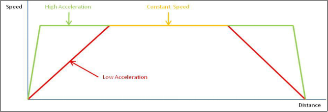
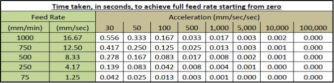
The above shows the effect of acceleration values on the time for the router to get up to speed depending on the feed rate assuming the spindle or laser is at rest to start with. So if you start a line from rest at a feed rate of 1000 it will take over a second before it is at full speed. With that being the case, it is no wonder the burn is heavier!
Grbl does include compensation for this when Laser mode is set, but could really do with further tweaking. These settings ONLY determine the acceleration of the spindle, letting the spindle reach its specified rotational speed is totally separate. Consider making an ‘air cut’ for a few mm before encountering the stock, the spindle would already be rotating at full speed and moving at the specified speed before encountering the stock. Remember the board could be trying to move a big spindle motor, for bigger machines.
Apart from how fast an axis can be accelerated by its stepper motor this should have no effect on anything else. It should be noted that unless you are only moving the spindle along in a single axis at a time the acceleration values on all the axes it is moving in will affect each other. Imagine a 45˚ movement on X and Y, the spindle can only be accelerated as fast as the lower of the X and Y accelerations to keep the line straight. One last thought is that the masses of the spindle and mounting, the bed+clamps and stock probably will be different so affecting the acceleration, just as on the Z axis when moving up has to lift the mass of the spindle motor and mount, going down should be easier.
Within the linked Zip file at the top of this guide, you can try out a number of different acceleration values and find the one that suits you best, but for those not looking to experiment, try setting $120-122 values to 5000 for nominal results.
Tracing Test & The SpreadSheet
One of the attached files is a spreadsheet capable of generating Gcode for variations of the image below:

It is set at 20mm square by default and mixes horizontal, vertical, diagonal and circle movements, G0 (rapid non cutting movements) and G1 (cutting movements) so it should be fairly easy to see if the stepper motors are stalling and missing steps by the lines becoming misaligned. It is worth noting that the circle is only approximately aligned with the lines, so don’t worry if it seems a little off.
A series of these cannot be cut in a single .nc file as Grbl objects with varying parameters such as $120 in the middle of a GCode file. Instead the file ‘LaserAccelerationTest-xxx.nc’ produced from the spreadsheet just sets the acceleration ($120-122) values to xxx and draws a single shape, then positions the laser ready to start another one to its right.
Numerous .nc files are also provided for testing with a spindle motor and an engraving or V bit, these are SpindleAccelerationTest-xxx.nc
If you want your own values in the .nc file for your own tests either edit one of the .nc files to change the $120-122 lines between each box or delete these lines completely and change the settings before each run manually using console commands. Using the spreadsheet is easier but you have to have MS Excel.
To set it up you need to:
1. Set the WCS origin position.
2. Run the program.
3. Load the next .nc file with higher acceleration values.
4. Repeat.
The WCS origin for this is the bottom left. Any missed steps will be cumulative and should be easily visible.
This will only test the X and Y axes but that should be a good start. These are the results: From top left the acceleration values are 30,60,120,200,500 then on the second row 750, 1,000 5,000 10,000 and 100,000.
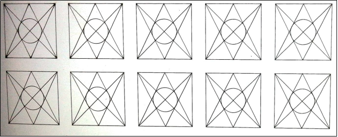
Examining this, at the default of 30 mm/sec2 all of the vertices are burnt, including the circle (which starts cutting through on its middle left). At an acceleration of 500 mm/sec2 (top right) all of this has largely disappeared and the cut is much cleaner. 5,000 mm/sec2 sees the last remnants of a thicker line on the left of the circle disappear, From then on there is no real discernible difference for this test. It is very important to note that at any setting there was no misalignment of the lines which means no missed steps!
$110-2 (Maximum feed rate)
From the Grbl Configuration guide: $110, $111 and $112 – [X,Y,Z] Max rate, mm/min
This sets the maximum rate each axis can move. Whenever Grbl plans a move, it checks whether or not the move causes any one of these individual axes to exceed their max rate. If so, it'll slow down the motion to ensure none of the axes exceed their max rate limits. This means that each axis has its own independent speed, which is extremely useful for limiting the typically slower Z-axis.
The simplest way to determine these values is to test each axis one at a time by slowly increasing max rate settings and moving it. For example, to test the X-axis, send Grbl something like G0 X50 with enough travel distance so that the axis accelerates to its max speed. You'll know you've hit the max rate threshold when your steppers stall. It'll make a bit of noise, but shouldn't hurt your motors. Enter a setting a 10-20% below this value, so you can account for wear, friction, and the mass of your workpiece/tool. Then, repeat for your other axes.
NOTE: This max rate setting also sets the G0 seek rates.
The default Values were $110=1000, $111=1000, $112=800 mm/min.
Does The Z Axis Have a Lower Default Value?
The documentation says it is ‘typically slower,’ but on the 3018-PRO and PROVer it has the same pitch on the threaded rod and the same stepper motor and motor driver so it shouldn’t apply. The Z axis movement speed would typically match up to the Plunge rate, the rate the bit heads straight down into the stock.
Too fast would be bad, but remember these are Maximum rates; they won’t make the slightest bit of difference unless your GCode specifies a feed rate greater than the maximum, in that case the maximum feed rate will be used instead.
A Simple Feedrate Test
The Maximum Feed rate is how fast the router can be told to move one or more axes without the motor missing steps. So here is a method to find out what this is:
1. Open Candle and connect to the router.
2. Set the $110-2 values to something high, 3000 should be plenty, by sending $110=3000 $111=........ as separate commands to the router. If you don’t do this the existing max federate settings will override any higher values rendering this test useless.
3. Position the spindle somewhere towards the middle on all axes.
4. Set the Jog Step to 10mm, other values are fine and work but 10mm is enough.
5. Set the Jog feed rate to the value to test, I suggest starting at 1500 and going up in 100’s to start with.
6. Now Jog left then right (or right then left, it doesn’t matter) and see what happens.
7. If everything works fine, no funny noises and more importantly the spindle moves as expected, increase the feed rate and try again. Eventually as the feed rate gets larger you will hear the stepper motor make a squeaky noise and the axis will not move properly. You have now exceeded the feed rate on the axis!
8. Repeat for the Y and Z axes.
Some notes on this:
- Make a note of the number or try different feed rates between the last value that worked and the one that failed. Then make a note of the highest number that worked with the axis you were testing.
- It is not important to be exact here as when this process is finished we are going to apply a margin for safety so it’s not really important if it's 2249 or 2251.
These are the values that were settled on as this guide was made:
X | 2100 |
Y | 2200 |
Z | 2150 |
To determine the maximum Feed rate you should take the Lowest value, multiply it by 0.8 to reduce it by 20% for safety. Now round it to a convenient number, such as 2000 instead of 2014.95
This is your new maximum federate value, set this by sending $110=yyyy then $111=yyyy then $112=yyyy to your router. Now as a final test, jog the spindle around to the (near) limits of travel on all the axes, there should be no problems at all.
For those not wanting to experiment, the final values for $110-112 was 1600 mm/min.
$30 and $31 (Spindle RPM)
From the Grbl Configuration guide: $30 - Max spindle speed, RPM
This sets the spindle speed for the maximum 5V PWM pin output. For example, if you want to set 10000rpm at 5V, program $30=10000. For 255rpm at 5V, program $30=255. If a program tries to set a higher spindle RPM greater than the $30 max spindle speed, Grbl will just output the max 5V, since it can't go any faster. By default, Grbl linearly relates the max-min RPMs to 5V-0.02V PWM pin output in 255 equally spaced increments. When the PWM pin reads 0V, this indicates spindle disabled. Note that there are additional configuration options are available in config.h to tweak how this operates.
$31 - Min spindle speed, RPM
This sets the spindle speed for the minimum 0.02V PWM pin output (0V is disabled). Lower RPM values are accepted by Grbl but the PWM output will not go below 0.02V, except when RPM is zero. If zero, the spindle is disabled and PWM output is 0V.
NOTE: The 0.02V and 5V referred to here is the output of the Arduino processor which works at 0-5V, on the router motherboard this is then fed into an ‘amplifier’ which converts into the 0-24V fed to the spindle motor. Just mentioning it.
The default Values are $30=1000, $31=0 RPM.
Maximum spindle Speed - $30
First and foremost, changing the maximum spindle speed will not make your spindle rotate any faster!
The spindle speed is controlled by PWM, or Pulse Width Modulation. This is the process of turning the electrical output on and off very rapidly in order to simulate an output power or voltage, this is what drives the Spindle motor or Laser.
When it's totally on the power is 100% equivalent to 24V, when it's all off the power is zero, equivalent to 0V. If in the middle then it’s on half the time and off the other half so that would be 50% power, equivalent to 12V. The Grbl motherboard can alter this in a total of 255 steps from 0 which is always off to fully on. So if the maximum spindle speed is 1000 then the 'speed' will rise in steps of approximately 4 RPM.
Why is the maximum Spindle speed normally set to 1000?
Grbl was designed as a small and cheap CNC controller, it still is.
It is not specific to any manufacturer, make or model. As such it has a set of values for parameters like this which by default are set on the conservative side so 1000 was selected as the default value for the Spindle speed.
Most people don't change these values, they are more concerned with the results and for nearly all measuring the actual spindle speeds achieved by their machine is not an option. You could compare it to the speedometer in your car, either calibrated in kph or mph. The speed you are travelling at is the same, it’s just the number that is different!
So 1000 is the de-facto standard value, and the‘standard' spindle motor on the 3018-PRO at full power (24V) rotates at just over 8,200 RPM under no load.
This being the case there are some pro's and con's to changing the value:
- Makes it easier to understand what is actually going on. (+)
- If using a speed and feed calculator or guide you should use the actual RPM. (+)
- It makes portability of GCode across machines easier, if I want the spindle speed to be 4000 then I can set it to that, if another machine has a faster or slower motor then the RPM will stay the same (+)
- A lot of Gcode files assume S1000 is the maximum RPM. (-)
- Others may generate GCode with the same assumption (Guilty as charged) (-)
- It affects the Laser power as well (-)
Rather than improving anything in regards to performance, it is more a matter of personal preference. If you want to be able to set your spindle speed by RPM, change $30 value to 8,000 and make sure that the maximum laser power is set the same in any software I may use to generate GCode for a Laser. But otherwise, leave it alone since you are probably already used to it being at 1000 anyways.
Minimum spindle Speed -$31
It sets the speed below which the spindle will turn at its slowest possible RPM. As mentioned before the controller changes the speed in a series of steps, anything below this value (excluding 0) will turn the spindle at its lowest possible speed. There is no need to change this.
How is a Laser affected by $30 and $31
Many users frequently swap the spindle motor and the laser module, so its good to have a set of settings that work with both. Admittedly, Laser mode ($32) needs changing each time, but there is no need to totally reconfigure everything each time you swap them.
A laser does not have an RPM, just a power setting. The GCode ‘standard’ has refused the spindle speed command to also control the Laser power. So a GCode of S500 with a spindle is supposed to mean 500RPM, if you are using a Laser then the laser power will be set according to the percentage of the $30 setting. If $30=1000 then the laser power setting would be 500/1000 = 50%, if $30=8000 then the laser power setting would be 500/8000 = 6.25%. A big difference!
You need to make sure that any software that you use to generate GCode has the same maximum power setting as the $30 value.
$130-2 (Maximum travel settings)
From the Grbl Configuration guide: $130, $131, $132 – [X,Y,Z] Max travel, mm
This sets the maximum travel from end to end for each axis in mm. This is only useful if you have soft limits (and homing) enabled, as this is only used by Grbl's soft limit feature to check if you have exceeded your machine limits with a motion command.
BUT The description of the homing cycle also says:
Finally, ensure your $13x max travel settings are somewhat accurate (within 20%), because Grbl uses these values to determine how far it should search for the homing switches.
Essentially, these settings are only used if you have endstops and a home position. If that is the case, then you need to set these to the limits of your machine.
They seem to be used for 2 purposes.
1. How far the machine can expect to travel when trying to find the home position during a homing cycle.
2. Once the home position is set the limits the machine can travel when Soft Limits are enabled.
The values for the second purpose need to be precise. These should take account of the home position, how much travel the limit switches themselves take up, this is due to their positioning and the 'bounce back' value the machine uses once a switch has been triggered.
In Summary
Value | Meaning | From | To | Benefits / Effects |
$120-$122 | Acceleration | 30 | 5000 | Reduced job times and cleaner laser lines. Nothing else is affected. |
$110-$112 | Max Feed Rates | 1000 | 1600 | You can go faster if you want to. Nothing else is affected. |
$30 | Max Spindle Speed | 1000 | 8000 | More accurate, can use speed and federate more easily. BUT this affects imported GCode and CAM software settings, especially for a Laser. |
$32 | Laser Mode | 0-1 | 0-1 | Set to 1 when a Laser is being used, set to 0 when a Spindle motor is being used. |
$130-2 | Max Travel | 200/200/200 | 290/170/40 | Not used without the Homing set. |