Assemble your Genmitsu 3018-PROVer

- Part 1 - Unboxing
- Part 2 - Mechanical installation
- Part 3 - Wiring
- 3.1 Install the Main Control Board
- 3.2 Install the Acrylic Baffles
- 3.3 Connecting X-Axis Limit Switches
- 3.4 Connecting Y-Axis Limit Switches
- 3.5 Connecting Z-Axis Limit Switches
- 3.6 Connecting the Stepper Motor cables
- 3.7 Connecting the Spindle cables
- 3.8 Install the Emergency Stop button
- 3.9 Cable Management(Optional)
- Installing drivers and starting your first project
Part 1 - Unboxing
Please make sure all the following parts are included. If you are missing any part or have any questions, please email us at support@sainsmart.com
Click here to go straight to assembly if you are feeling adventurous
- 1 x X-Axis/Z-Axis Gantry
- 1 x Y-Axis Base Assembly
- 1 x Spindle with ER11 tail
- 1 x ER11 1/8" Collet
- 2 x Acrylic Baffle
- 1 x Offline Controller
- 1 x Main Control Board
- 1 x USB A-to-B Cable
- 1 x Power Supply
- 1 x Power Adapter Cable - US
- 1 x Power Adapter Cable - EU
- 4 x Limit Switch
- 1 x Offline Controller Cable
- 1 x Limit Switch Cable X LIM+, 15cm
- 1 x Limit Switch Cable X LIM-, 53cm
- 1 x Limit Switch Cable Y LIM+, 30cm
- 1 x Limit Switch Cable Y LIM-, 60cm
- 1 x Limit Switch Cable Z LIM-, 34cm
- 1 x Limit Switch Cable Z LIM-, 40cm
- 1 x Stepper Motor Cable, X-Axis, 17cm
- 1 x Stepper Motor Cable, Y-Axis, 52cm
- 1 x Stepper Motor Cable, Z-Axis, 28cm
- 1 x Spindle Cable, 35cm
- 1 x Emergency Stop Button with Cable
- 1 x Work Clamp Set
- 1 x Z-Probe Kit
- 10 x 20-degree V Bit
- 1 x Allen Wrench Set, 2mm, 2.5mm, 3mm, 4mm, 5mm
- 2 x Wrench
- 1 x Screwdriver
- 1 x Spacer Template
- 30 x Cable Tie
- 10 x Cable Holder
- 1 x Sealing Strip, Y-Axis, 27cm
- 1 x Sealing Strip, X-Axis, 34cm
- 1 x Nylon Braided Cable Wrap
- 1 x MicroSD Card
- 1 x MicroSD Card Reader
- 1 x User Manual
- 4 x Rubber Foot
- 8 x M5 10mm Bolt
- 12 x M5 14mm Bolt
- 2 x M6 16mm Bolt
- 2 x M3 20mm Screw
- 16 x M3 5mm Screw
- 4 x M3 8mm Screw
- 4 x M3 20mm T-Slot Nut
- 8 x M5 20mm T-Slot Nut
- 12 x Tension T-Slot Nut
- 2 x ABS Spacer
Part 2 - Mechanical installation
In addition to this guide, you can watch this video and this video to see the actual assembly process.
2.1 Preparing your base assembly
What you will need
- Y-Axis Base Assembly
- (2) M6 16mm Screws
- 5mm Allen Wrench
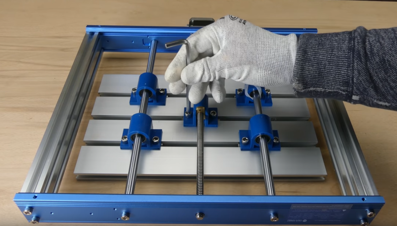
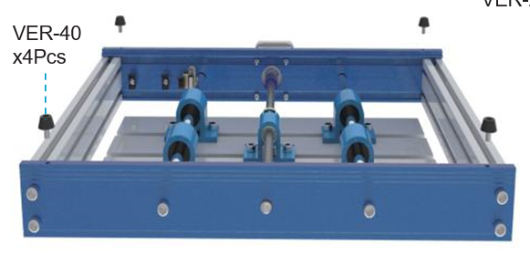
Step 1: Flip the Y-Axis Base Assembly upside down and remove the cable ties from the bearing mount
Step 2: Align the Aluminum Build Plate center slot with the blue Y-Axis lead screw mount as shown in the picture.
Step 3: Tighten (2) M6 16mm screws to secure the lead screw mount.
2.2 Installing limit switches & cable holders to Y-Axis
What you will need
- Y-Axis Base Assembly
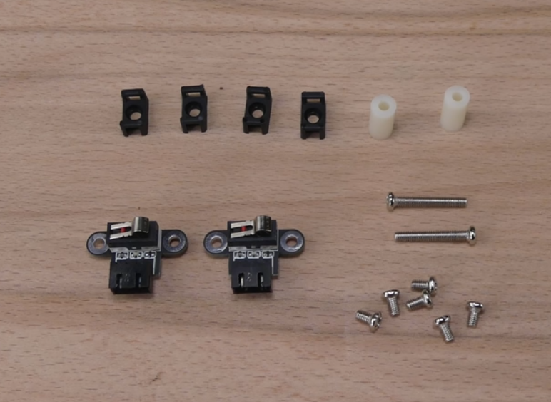
- (10) M3 x 5mm Screws
- (2) Limit Switches
- (6) Cable Holders
- M3 5mm Screwdriver
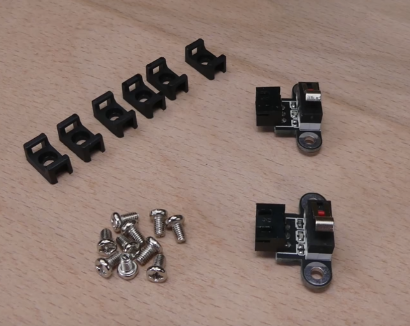
Step 1: Locate the Limit switch mount indents on the inner side of the frame. One on each side as shown below.
Step 2: Install cable wire holders in the pre-drilled holes next to the limit switches, using the 3mm screws. Install two cable holders on each side, facing inside the frame. Install two on the outside of the frame in the back (the stepper motor side)
Step 3: Install the limit switch by tightening the 3mm screws.
2.3 Installing Rubber feet to Y-Axis Base Assembly
What you will need
- Y-Axis Base Assembly
- (4) Rubber Feet
- 3mm Allen Wrench
Step 1: Locate the 4 pre-drilled holes and install the rubber feet on each corner using the Allen wrench
2.4 Installing Limit Switches to X-Axis/Z-Axis Gantry
What you will need
- X-Axis/Z-Axis Gantry
- (2) Limit Switches
- (3) Wire Holders
- (2) White ABS Spacers
- (2) M3 20mm Screws
- (6) M3 5mm Screws
- Screwdriver
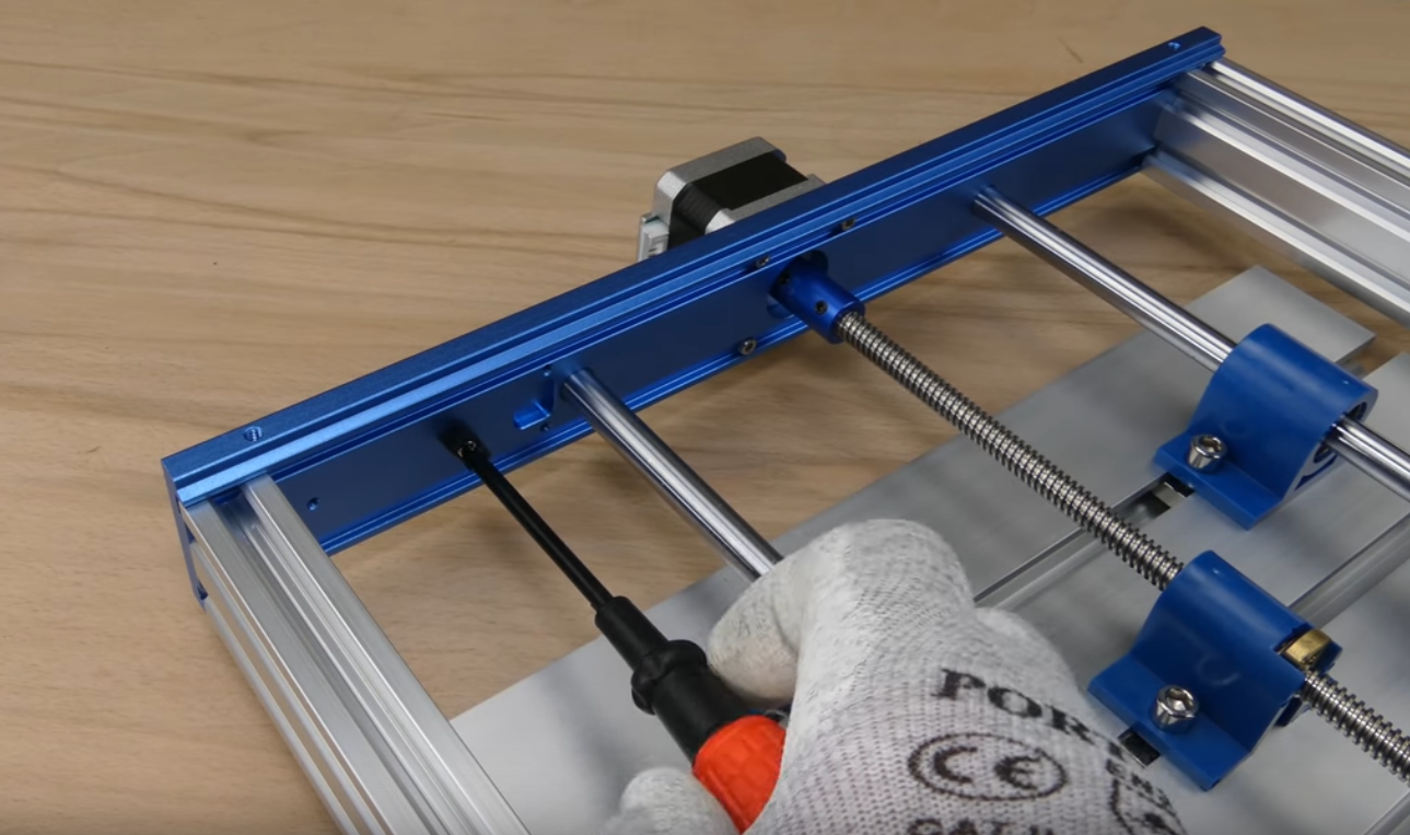
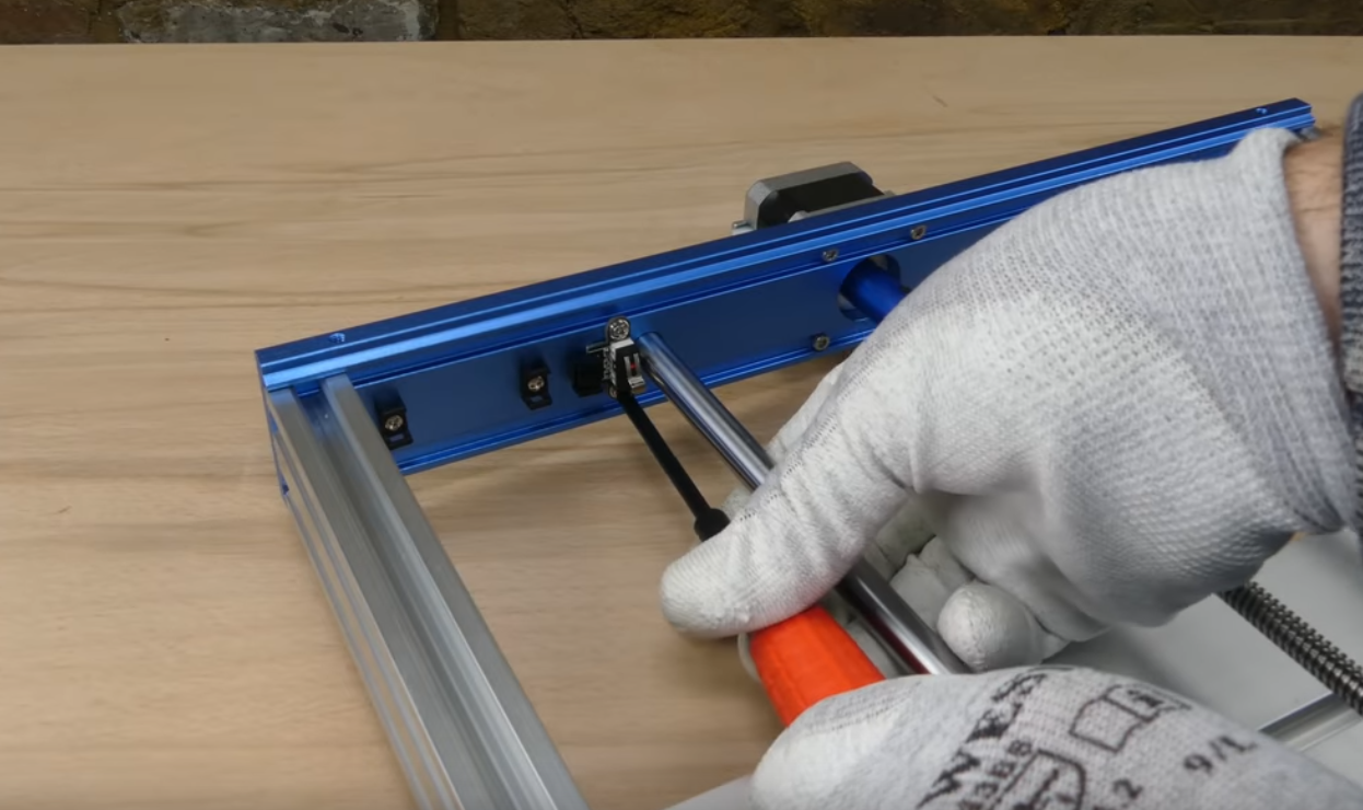
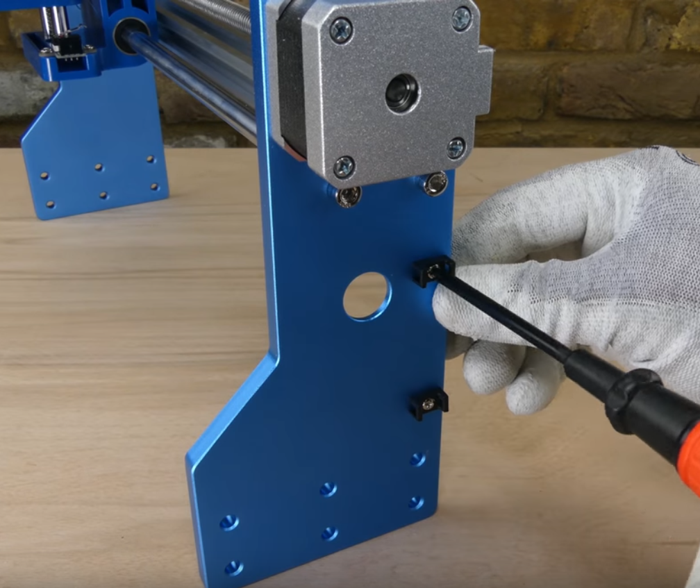
Step 1: The first limit switch to install is on the stepper motor side. You will need the two white ABS spacers and the longer 20mm M3 screws for this step. Locate the two pre-drilled holes on the inside of the gantry next to the lead screw, as shown in the picture below. Using (2) M3 20mm screws to secure the limit switch followed by the spacers into the frame.
Step 2: Install four cable holders on the same side of the gantry. Two on the inside and two on the outside.
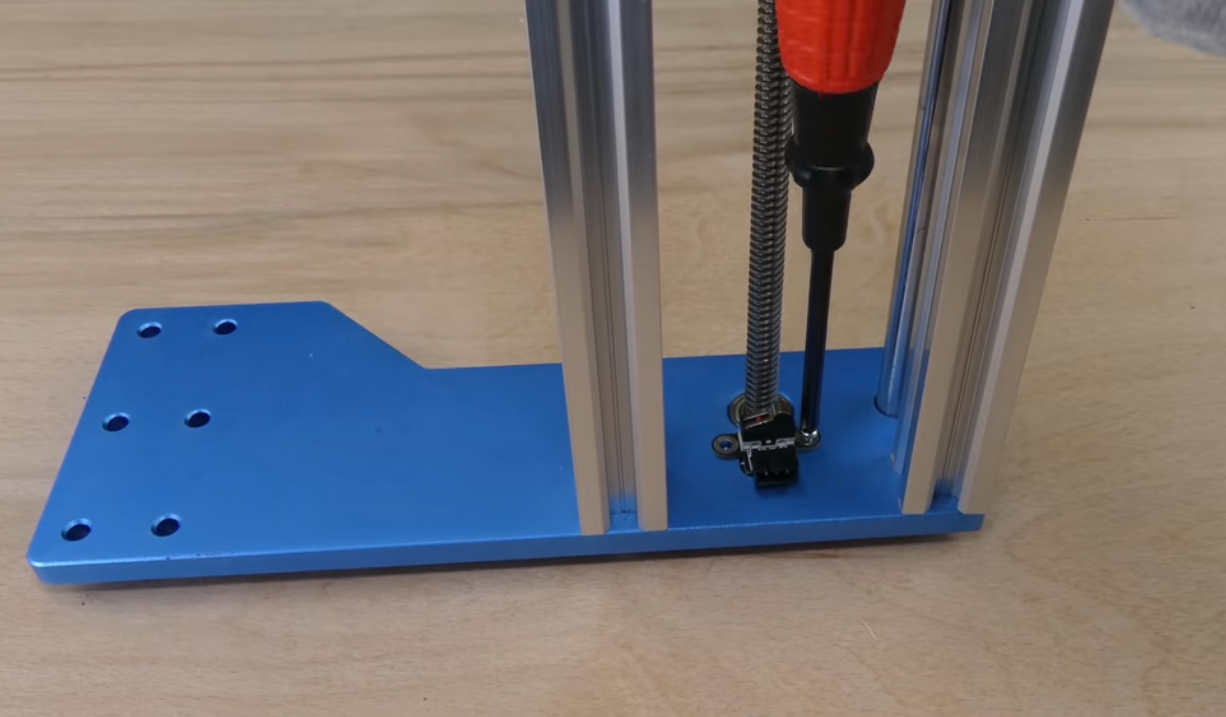
Step 3: Now install the remaining Limit switch on the opposite side, using the 5mm M3 screws. You don't need a spacer for this limit switch.
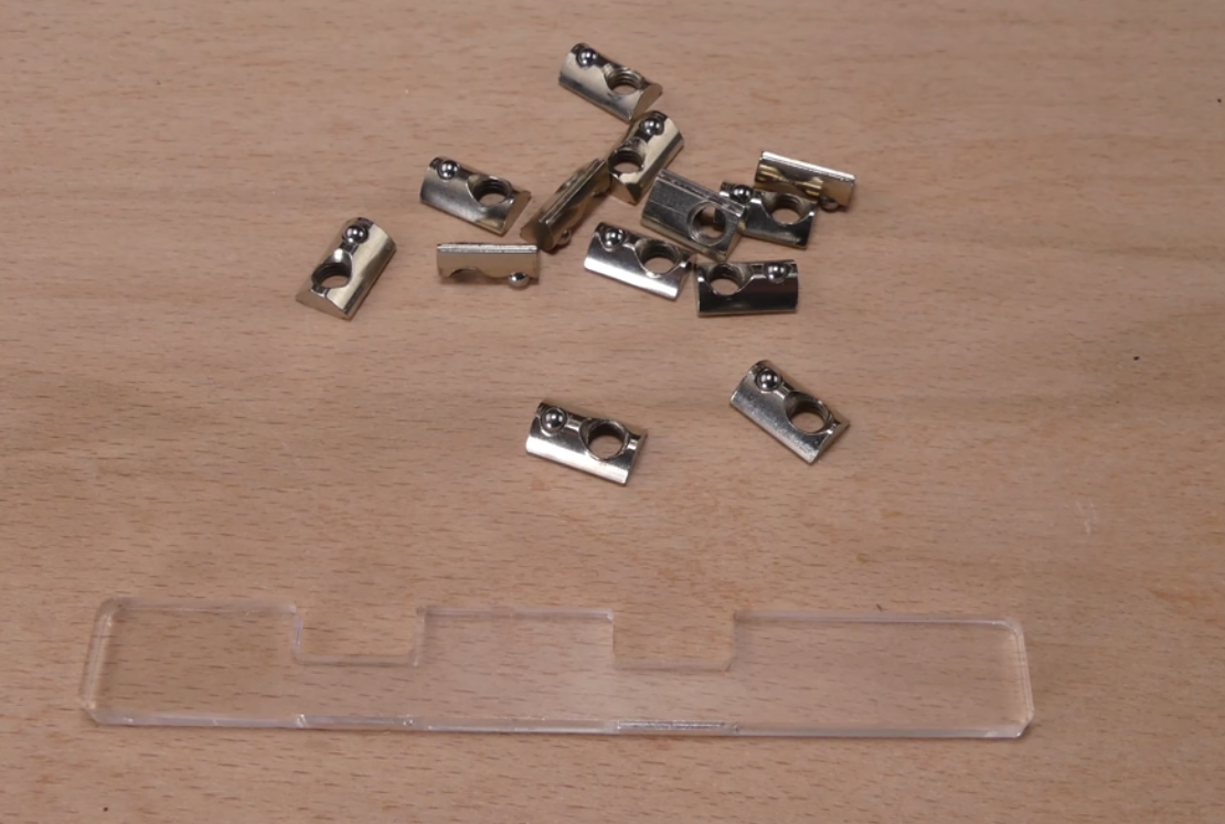
2.5 Install T-Slot Tension Nuts
What you will need
- Y-Axis Base Assembly
- (12) Tension T-Slot Nuts
- Acrylic Spacer Template
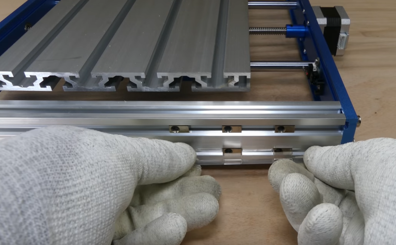
Step 1: Position the Y-Axis base assembly so that the step motor is facing your right hand side.
Step 2: Insert (6) Tension T-Slot Nuts on each side. Position near the back of the machine (Stepper Motor Side).
Step 3: Insert the Acrylic Spacer Template into the slot and space out the T-slot nuts as shown below. (Figure A). There should be a 31.5mm clearance(the longest space on the spacer) between the back T-Slot nuts and Rear of the machine as shown in the following picture.
2.6 Install Y-Axis Base to X / Z Axis Gantry
What you will need
- Y-Axis Base Assembly
- X-Axis / Z-Axis Gantry
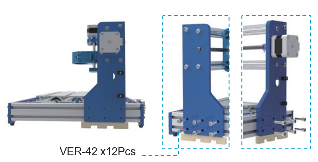
- (12) M5 14mm screws
- Acrylic Spacer Template
- 4mm Allen Wrench
Step 1: Set the X-Axis / Z Axis Gantry over your Y-Axis Base Assembly as shown below.
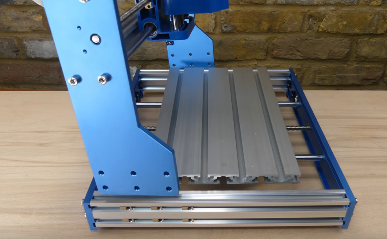
Step 2: Place the Acrylic Spacer template underneath the gantry to prop a side up at a time. See through the six pre-drilled holes on the side of the gantry to make sure they align with the nuts positioned in 2.5.
Step 3: Install (6) M5 14mm screws into the T-Slot nuts. Keep the screws loose until you finish the other side.
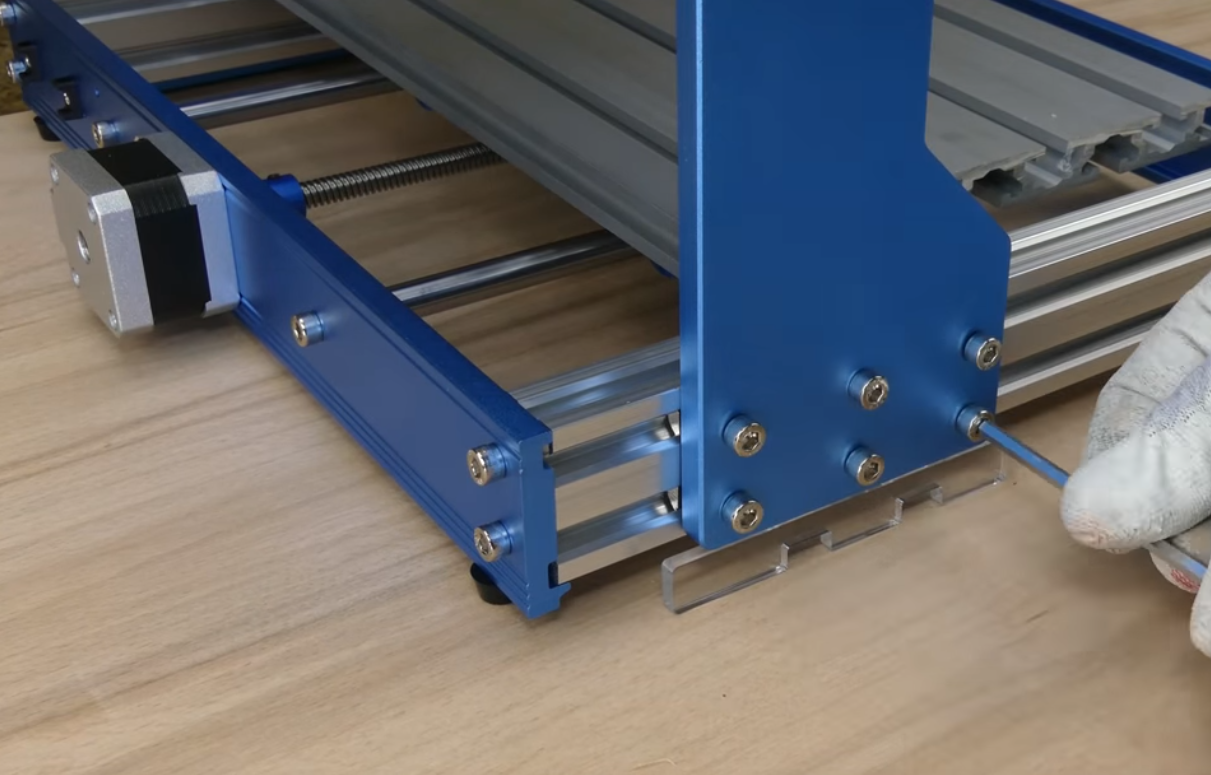
Step 4: Repeat the process on the opposite side. Now you can tighten all 12 M5 screws.
2.7 Install the Spindle
What you will need
- Spindle with ER11 tail
- ER11 1/8" collet
- 3mm Allen Wrench
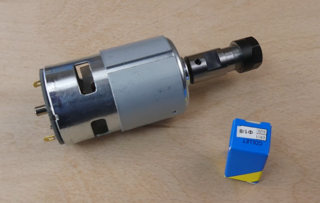
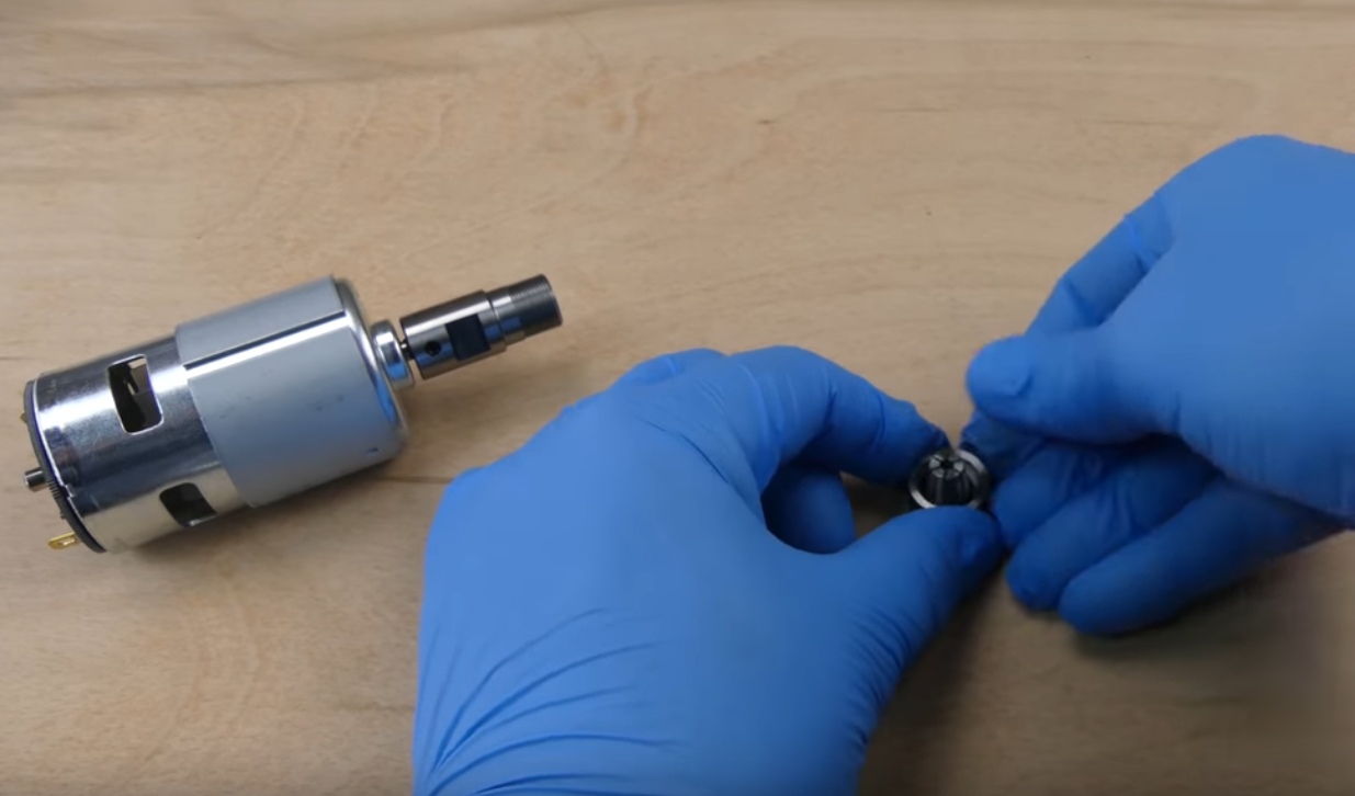
Step 1: Unscrew the black collet collar from the spindle and insert the collet. Make sure the collet is locked in place by pushing it. Then screw the the collet collar back to the spindle.
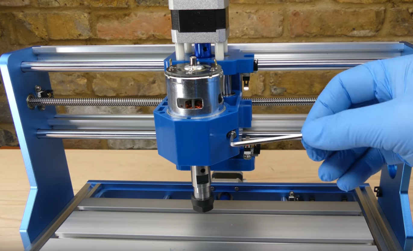
Step 2: Loosen the Spindle Mount Hex Screw
Step 3: Slide the spindle into the mount until the external sleeve of the spindle is fully inserted.
Step 4: Tighten the Hex screw to secure the Spindle. Do not over tighten the screw, as it can damage the mount.
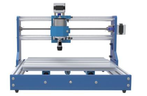
Congratulations! Now your machine frame is fully assembled!
Now let's move onto wiring!
Part 3 - Wiring
3.1 Install the Main Control Board
What you will need
- Main control board
- (4) M4 8mm Bolts
- (4) M3 20mm T-Slot Nuts
The main board goes to the back of the machine (the opposite side of the spindle). Remove protection paper tape from acrylic pieces on the main board.
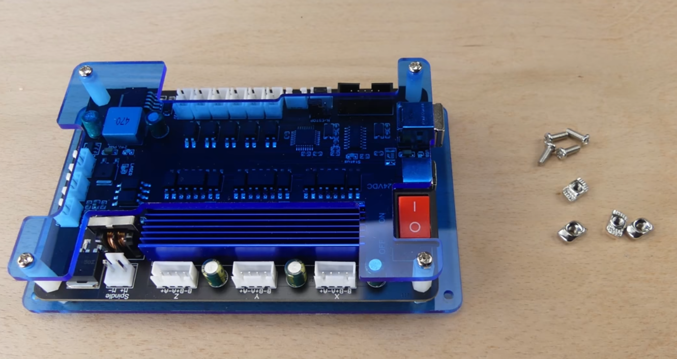
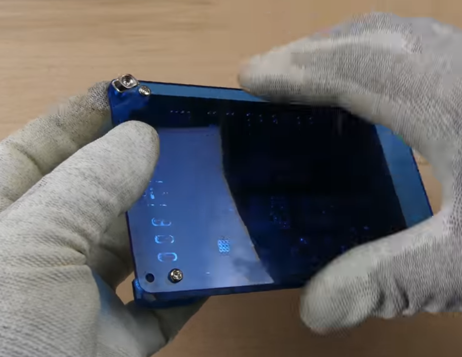
Step 1: Locate the four pre-drilled holes in the corners on the control board. Put on the M3 T-Slot nuts trough the holes into M4 8mm bolts. One turn only. Keep the nut loose and in horizontal position so that they can be inserted into the beams in step 2.
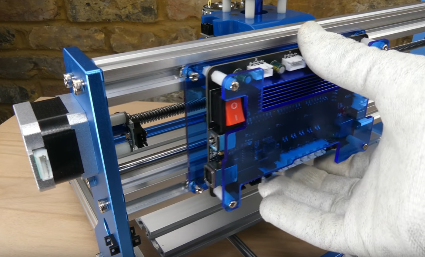
Step 2: Position the frame so that the back of the machine is facing you. Install the board by inserting (4) M3 20mm T-Slot nuts onto the top and bottom beams on the frame, like shown in the figure below.
Step 3: Slide the board horizontally to leave about 30mm of space between the board and the left edge of the machine as shown below.
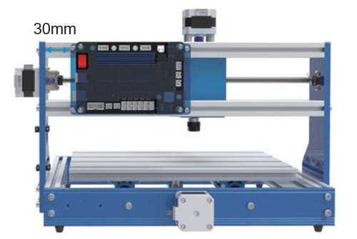
Step 3: Now you can tighten all (4) 8mm bolts so the T-Slot nuts lock the board into the frame.
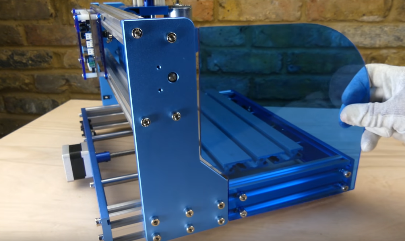
3.2 Install the Acrylic Baffles
What you will need
- (2) Acrylic Baffles
- (8) M5 10mm Bolts
- (8) M5 20mm T-Slot Nuts
- 4mm Allen Wrench
You want to identify the left baffle and the right baffle first, by placing the baffle along side the frame to fit the shape. Peel off the protective paper from the baffles.
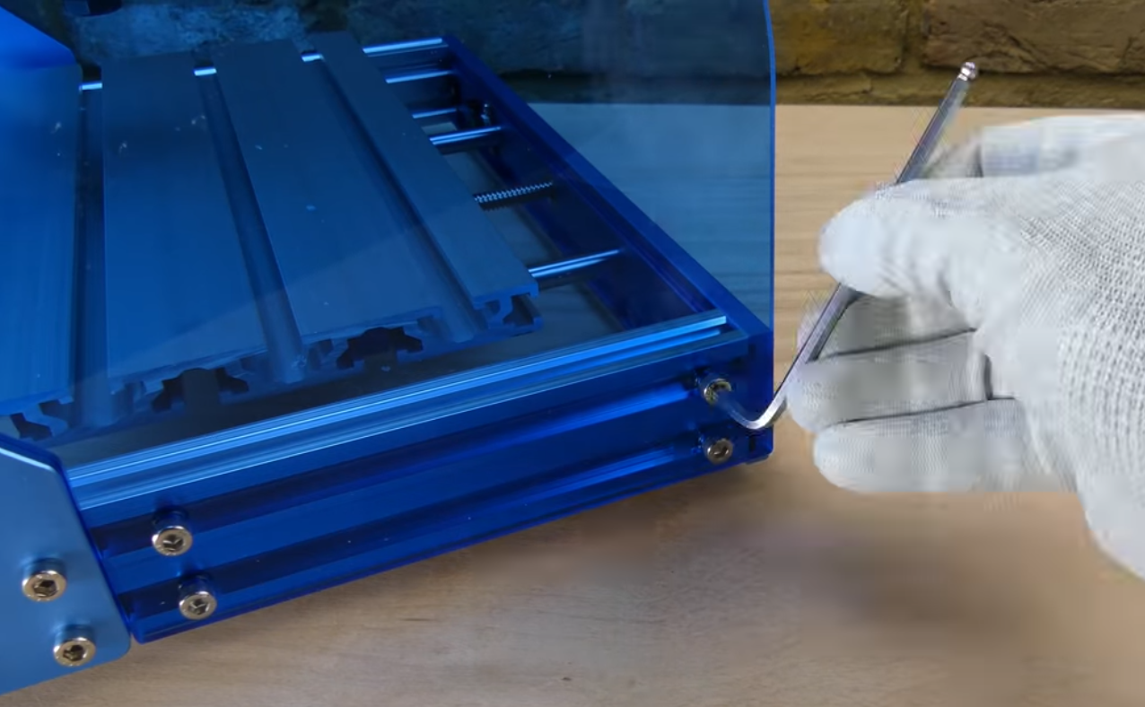
Step 1: Insert the M5 bolts from the outside of the baffle (For example, for the left-side baffle, the M5 bolt should insert from the left side). Then put the T-Slot nut onto the bolt from the other side using your hand. One turn only. Keep them loose for now. Orient the T-Slot nuts horizontally.
Step 2: Place T-Slot nuts into the side of the machine so that the baffle is aligned with the edge of the frame.
Step 3: Now tighten the M5 bolts to secure the baffle. Repeat the steps to install the other side.
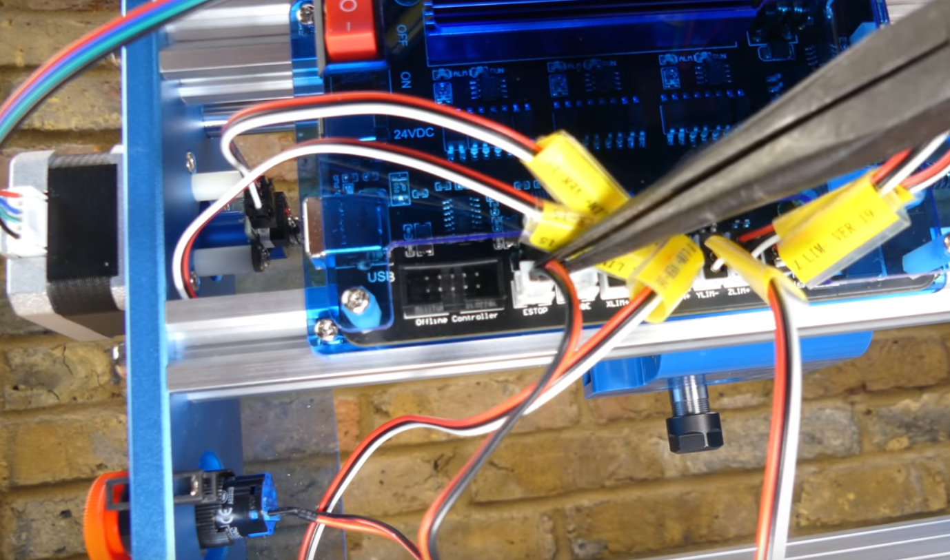
3.3 Connecting X-Axis Limit Switches
What you will need
- X-LIM+ 15cm Limit Switch Cable
- X-LIM- 53cm Limit Switch Cable
- X-Axis 340mm Sealing Strip
(Limit switch cables have black plugs on both ends)
Position the machine so that the main control board is facing you.
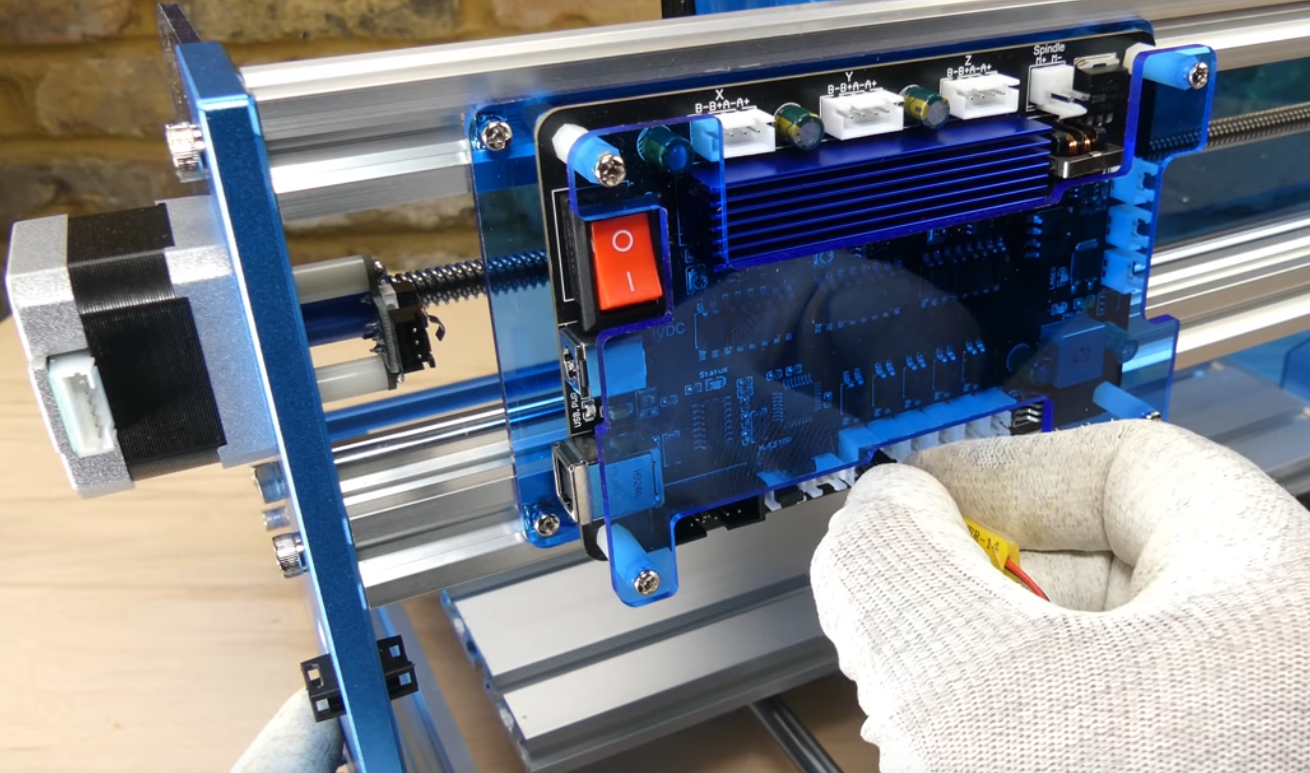
Step 1: Connect one end of the Limit Switch Cable X-LIM (+) (+ is near the stepper motor) to the X+ limit switch near the stepper motor, and connect the other end to the socket marked X-LIM (+) to the main control board (There are six white sockets toward the bottom of the board)
Step 2: Connect Limit Switch Cable X-LIM (-) to the X- limit switch on the right side. Run the cable behind the control board, along the top channel of the bottom beam, then loop around the control board. Plug the other end of the cable to the control board X-LIM(-) socket.
Step 3: Press the sealing strip (flat side out) over the cable into the top channel of the bottom beam.
3.4 Connecting Y-Axis Limit Switches
What you will need
- Y-LIM+ 30cm Limit Switch Cable
- Y-LIM- 60cm Limit Switch Cable
- Y-Axis 270mm Sealing Strip
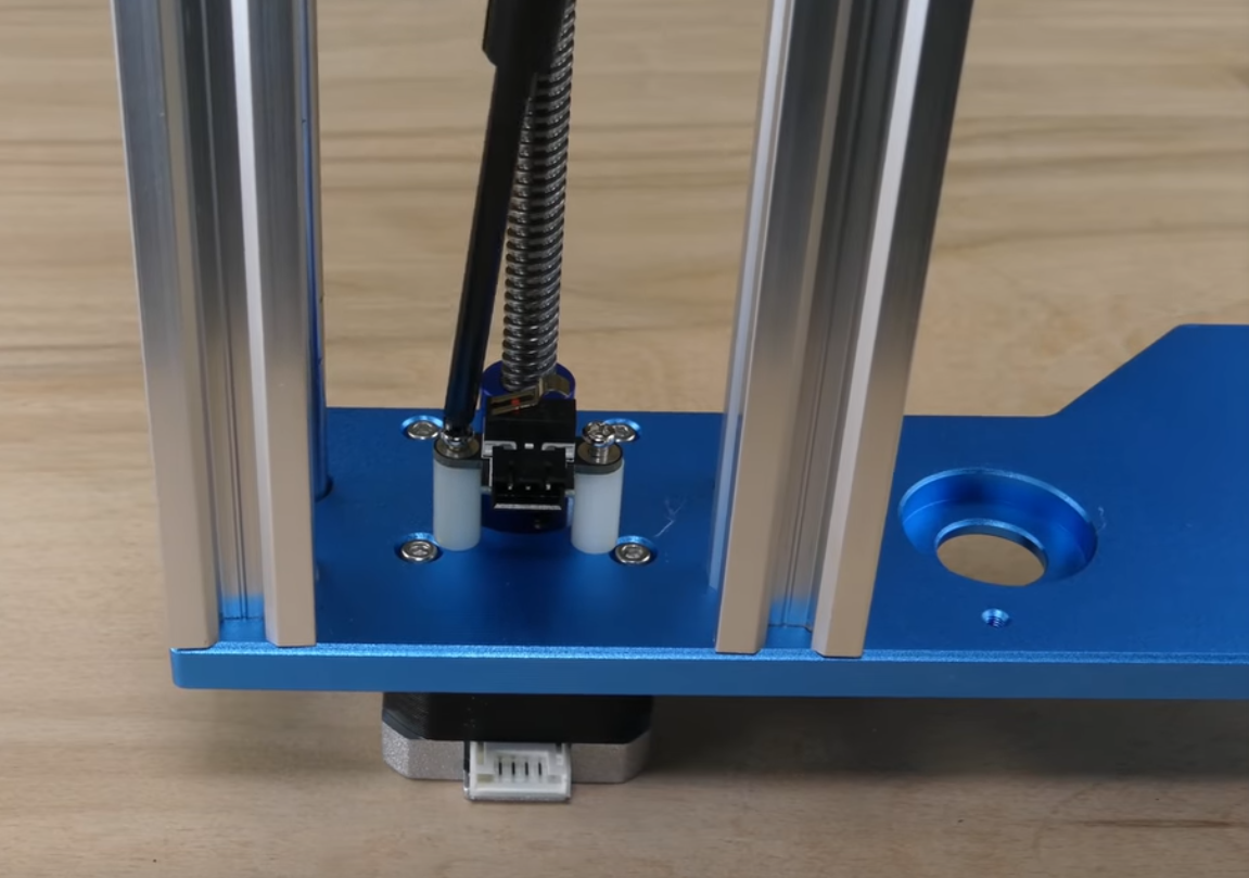
Step 1: Connect one end of the Limit Switch Cable Y-LIM (+) to the Y+ limit switch (the one on the step motor side)
Step 2: Connect one end of the Limit Switch Cable Y-LIM (-) to the Y- limit switch
Step 3: Connect both cables to the corresponding sockets on the control board
Step 4: Press the sealing strip (flat side out) over the Y- limit switch cable into the side beam.
3.5 Connecting Z-Axis Limit Switches
What you will need
- Z-LIM+ 34cm Limit Switch Cable
- Z-LIM- 40cm Limit Switch Cable
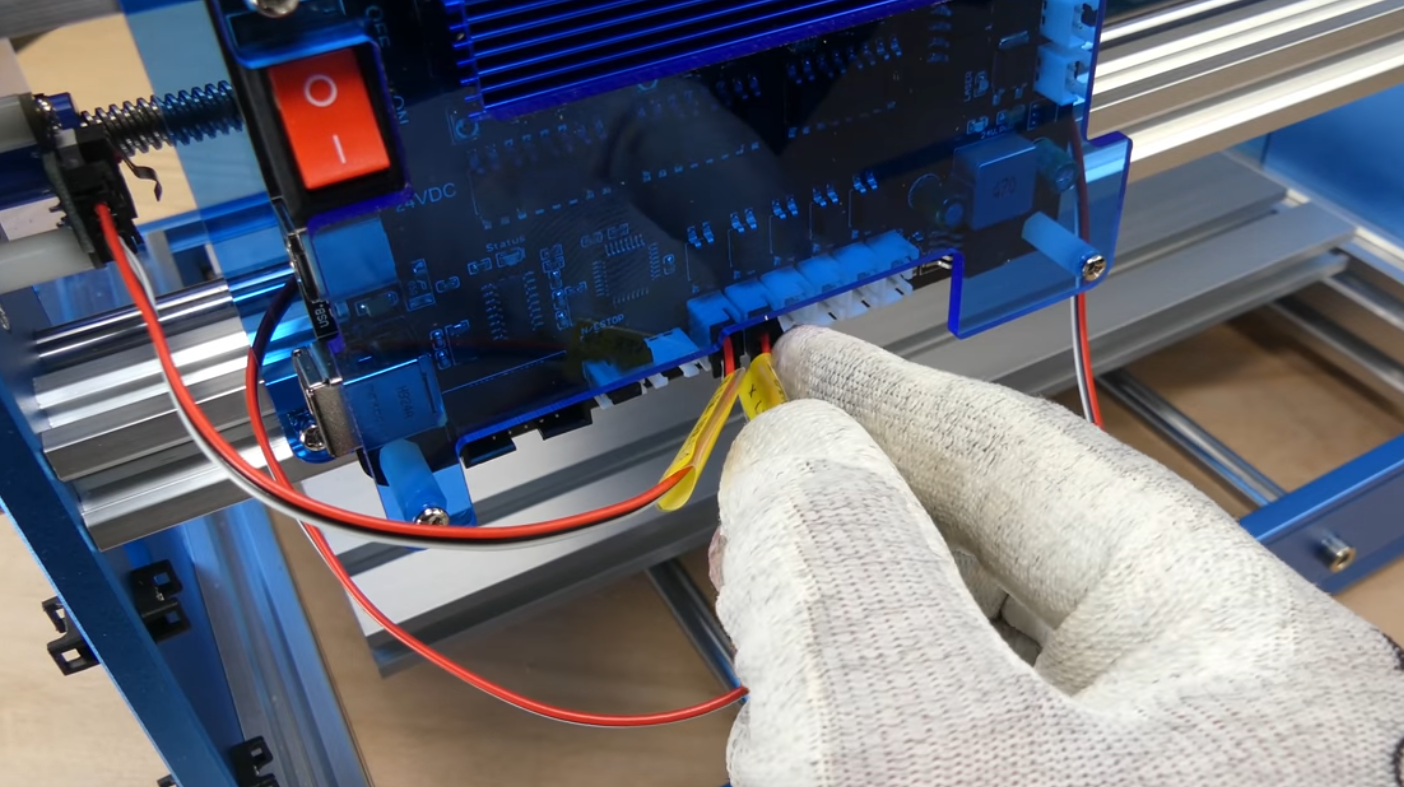
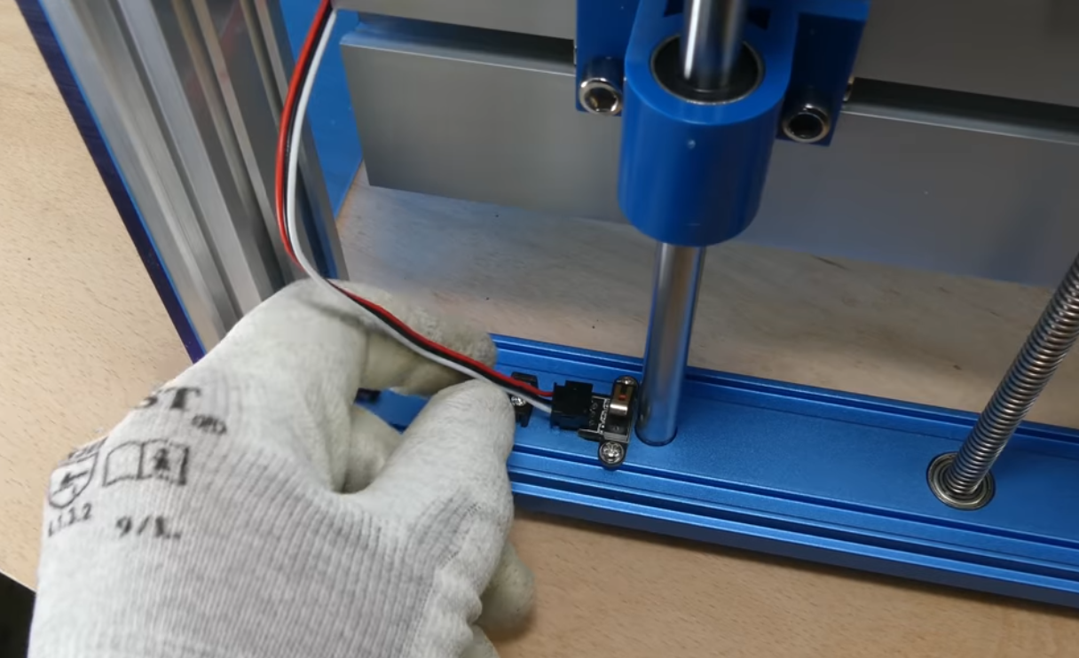
Step 1: Insert the short Limit Switch Cable Z-LIM (+) into Z+ limit switch(on top, near the stepper motor). Connect the other end to main control board.
Step 2: Insert the long Limit Switch Cable Z-LIM (-) into Z- limit switch(toward the spindle holder). Connect the other end to main control board.
3.6 Connecting the Stepper Motor cables
What you will need
- X-Axis 17cm Stepper Motor Cable
- Y-Axis 52cm Stepper Motor Cable
- Z-Axis 28cm Stepper Motor Cable
(Stepper Motor Cables are cables with white plugs on both ends)
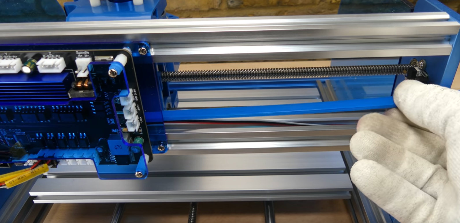
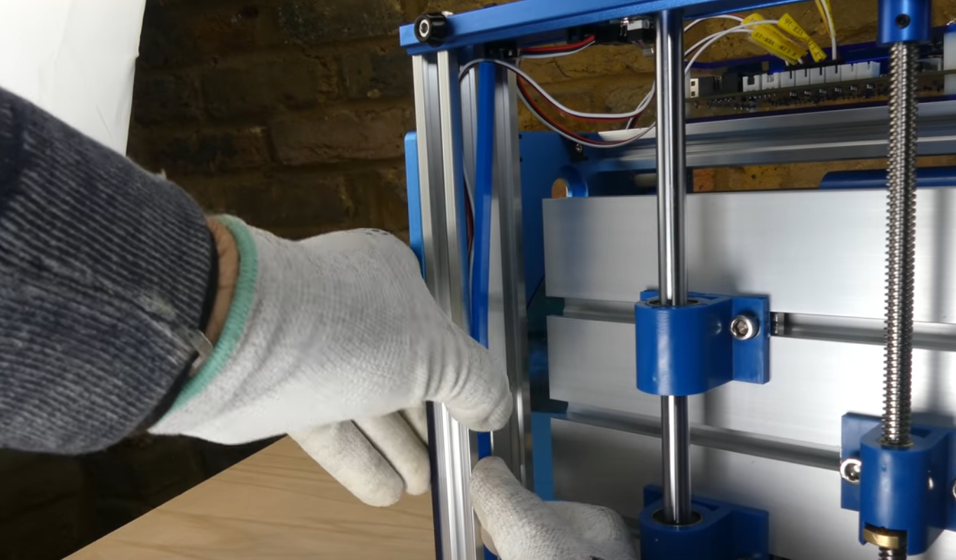
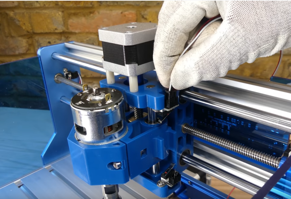
Step 1: Locate all three stepper motors. X-Axis stepper motor is on the side of the machine. Y-Axis stepper motor is on the bottom of the machine in the back. Z-Axis stepper motor is on top of the machine. As shown in the photos below.
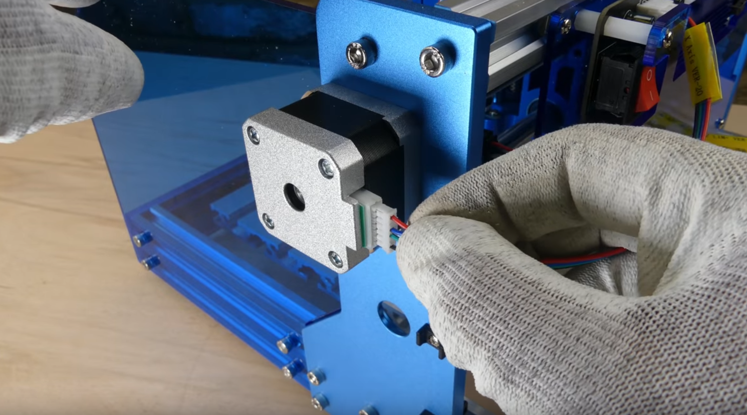
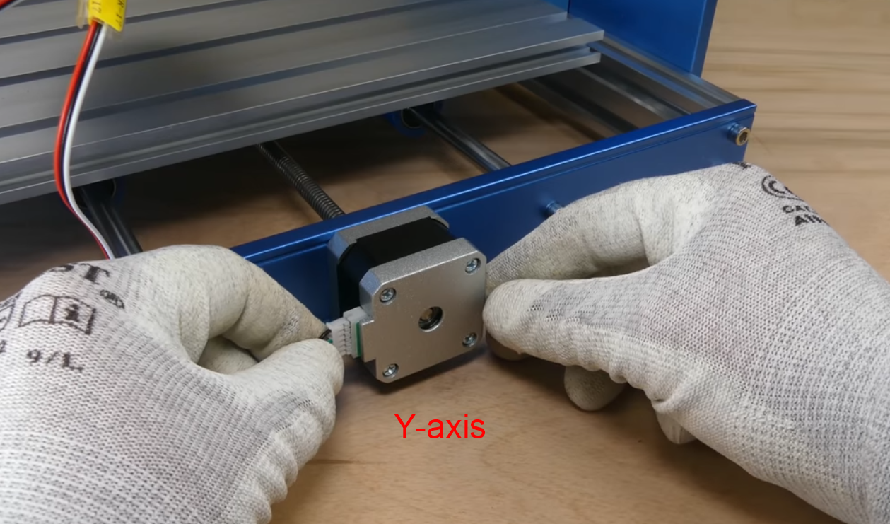
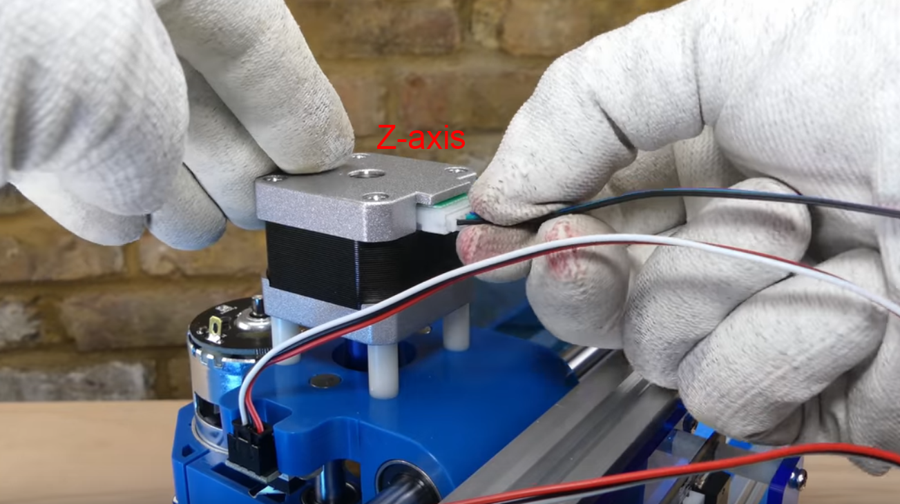
Step 1: Connect each stepper motor with the labeled cable to the main control board. Note that the end of 4-pin plug goes to the main board.
3.7 Connecting the Spindle cables
What you will need
- Spindle Cable 35cm
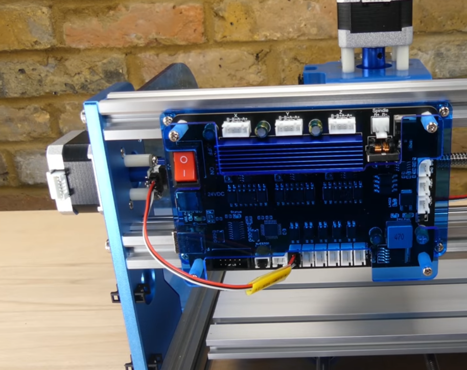
Step 1: Connect spindle cable to the top of the spindle, RED to M+ and BLACK to M-
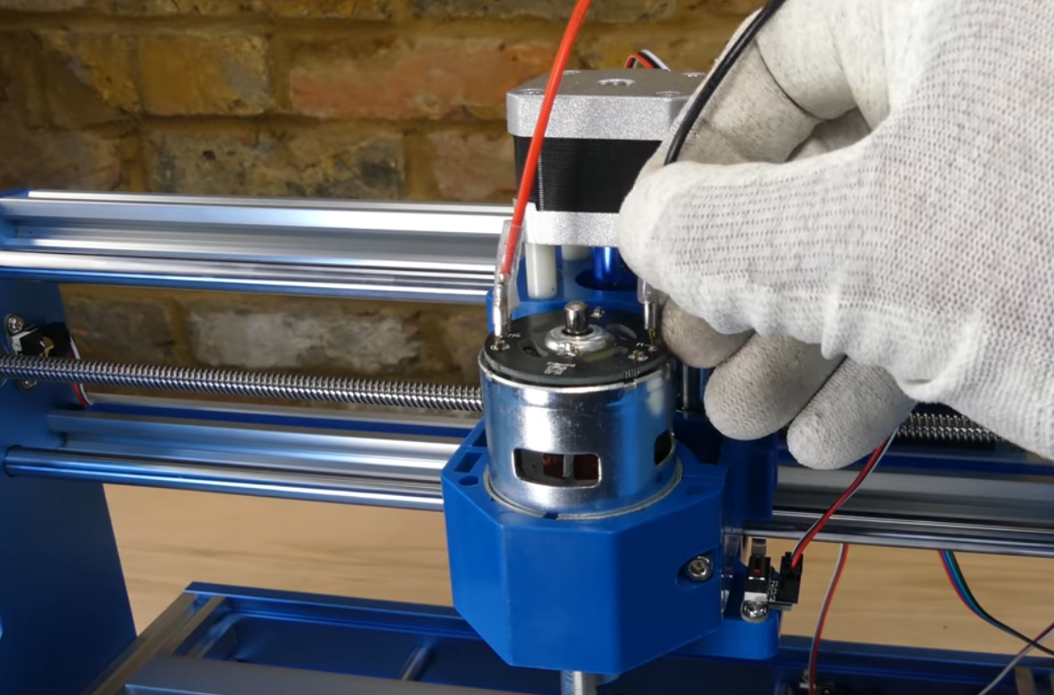
Step 2: Connect the other end of the spindle cable to the main control board
3.8 Install the Emergency Stop button
What you will need
- Emergency Button
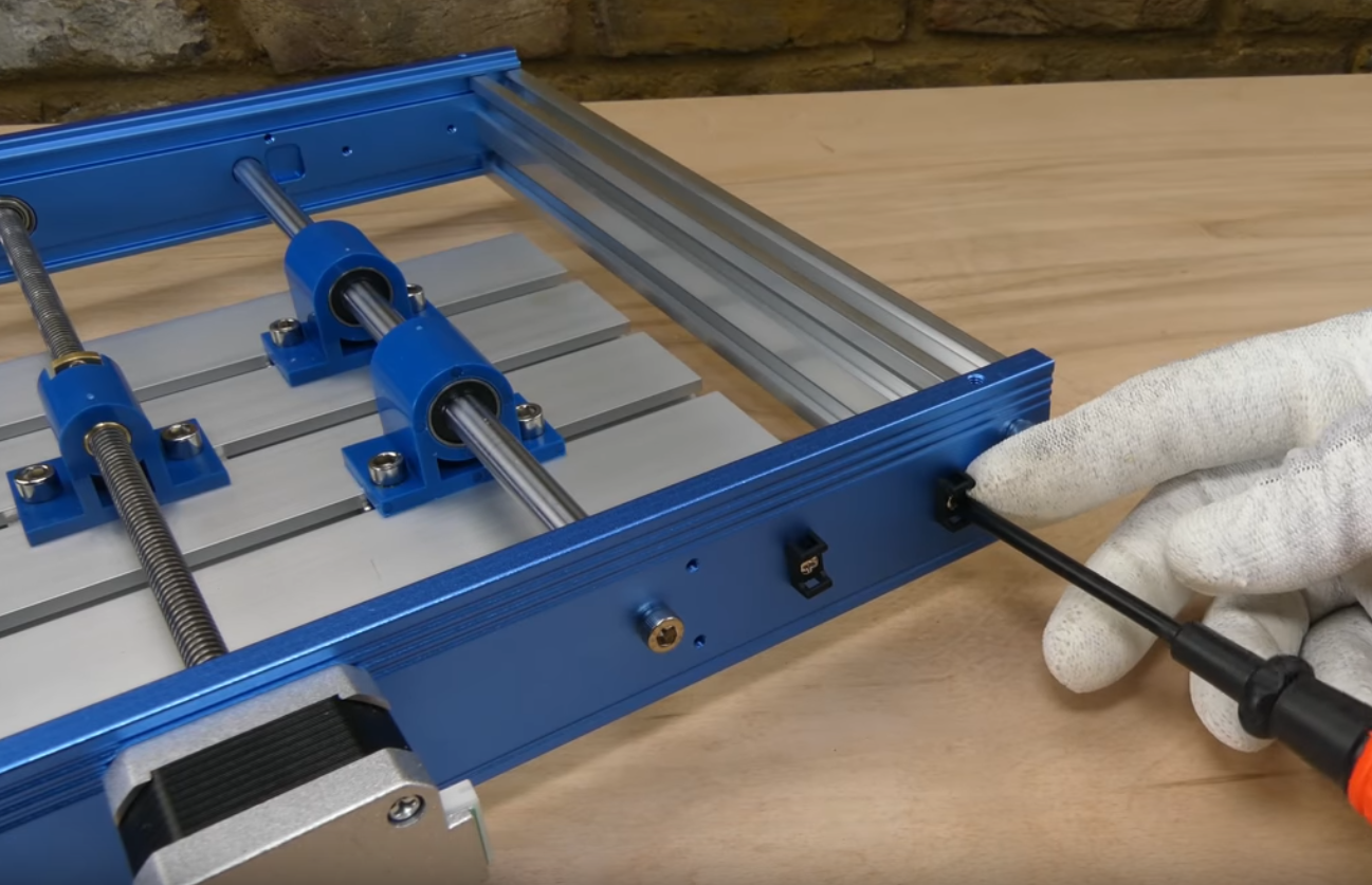
Step 1: Remove black plastic nut and the square lock washer on the back side of the button
Step 2: Insert Emergency button into the pre-cut hole underneath the X-Axis Stepper Motor. See Picture A.
Step 3: From the other side of the metal plate(inside), Install the square lock washer(with pointy corners facing the metal plate) then black plastic nut back onto the Emergency button and tighten down.
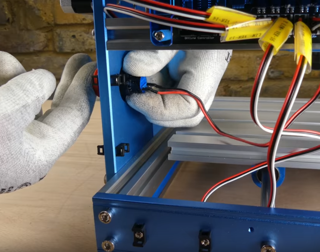
Step 4: Connect the cable to the main control board. See position show below.
Usage: Pushing the button will trigger emergency stop. The button will stay engaged once pushed. The button can only released when twisted clockwise. This prevents double pushing the button from releasing the trigger.
3.9 Cable Management(Optional)
Please refer to the video for cable management options.
Installing drivers and starting your first project
What you will need
(Click the following links to download the software)
Check out our CNC section for more guides and tutorials!