Making a Motor Noise Suppression (MNS) PCB for Your Sainsmart 3018 Pro CNC Machine
 Updated
Based off of the works of by Jim Kortge
The items you may need
Introduction
One of the nice new features provided by the PROVer is that it has a circuit board attached to the top of the motor to control noise coming from the motor getting back into the controller board. This guide, and the associated files are meant to allow owners of the 3018 Pro to implement this feature via a fun yet challenging project.
Project Explanation & Setup
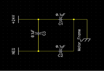
The PROVer MNS PCB uses capacitors across the motor leads, along with a capacitor on each lead to the frame of the motor. Additionally, the PROVer PCB has a Green LED and associated resistor to show when the motor is running and is also a polarity indicator.
This version only uses the 3 capacitors, to keep the design simple.
It was converted to a PCB layout in DipTrace using the features inherent in that program. A single mouse click creates a blank PCB, along with the parts. The user then arranges the parts as needed and defines the other attributes of the PCB such as the size, shape, and the milling operations needed to make them.
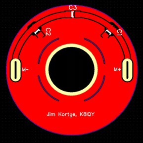
The actual size of the PCB has a diameter of 40 mm. 1206 size surface mount capacitors are used for C1, C2, and C3. The blue colored arc sections eventually get milled into cooling slots that match up with those on the motor.
Having created the PCB, the next step was to create Gerber files that describe the traces, pads, drills and mills to produce this board. Those operations were also done in DipTrace. The resulting Gerber files were then converted to G-Code (.nc files) using a software package called FlatCam.
Four .nc files were created, one to do the isolation milling, one to mill the 0.6 mm slots to allow the PCB to fit over the motor power tabs, one to mill the large hole in the center of the PCB, so that it fits over the motor upper bearing housing, and a forth file that does a circular cut around the perimeter of the PCB, and mills the cooling slots that correspond to those on the motor.
The PCB material is held to the spoil board by using double sided tape, quite similar to carpet tape. It holds the PCB blank securely, and additional single sided tape can be added around the perimeter of the PCB blank if in doubt that the double sided tape will do the job; just make sure that it is outside the work area and height map of your project. The spindle is running at maximum speed of 1000, whatever that is on your CNC machine. Typically, on the order of 8000 to 9000 RPM. Using a vacuum between operations is suggested, it clears the way for the next operation.
Finally, the actual production of the PCB was done on my CNC running the Candle control program. It is worth mentioning that the most important operation in producing a prototype PCB on a SainSmart CNC running Candle, is to create a Heightmap at the beginning of the process. The Height Map contains a mapping of the height variation of both the underlying spoil board and the PCB substrate itself. Without have the Height Map information to compensate for those variations, all of the milling operations will be less than optimal and may result in an unusable PCB.
Milling The PCB
Using the files linked in the introduction, the board was made as follows (In numerical order of 1 - 4)
Files Name | Images | Description |
1MNS-TopCopperV3.gbr_iso_cnc.nc | 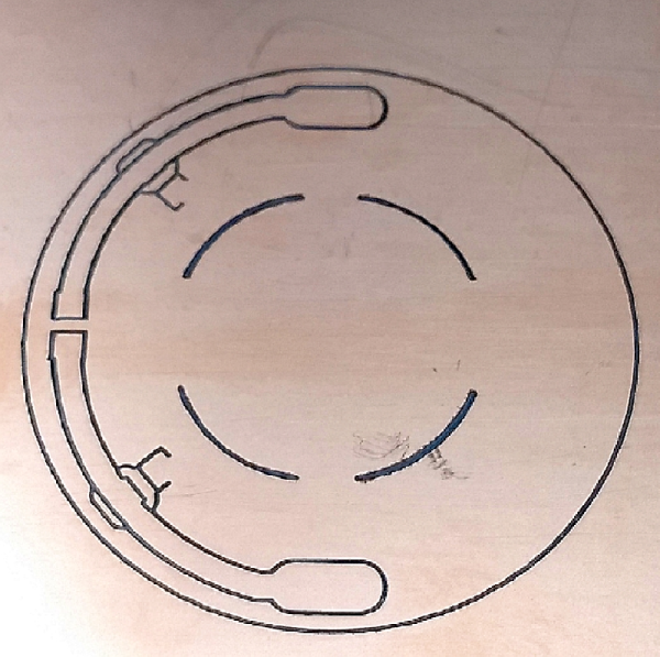 | The first operation was for isolation milling. A 0.1mm diameter tip, 20 degree V-bit was used for this, and prior to this operation, was installed in the spindle for creating the Height Map. The .nc file used for isolation milling specifies the cutting depth at 0.15 mm, the Z feed rate at 30 mm/minute, and the X-Y feed rate at 60 mm/minute. These are very conservative values, to keep the bit tracking where it should go, and not stressing the bit so that it breaks. |
2MNS-Through.drl_mill_slot_0.6mmCutter_cnc.nc | 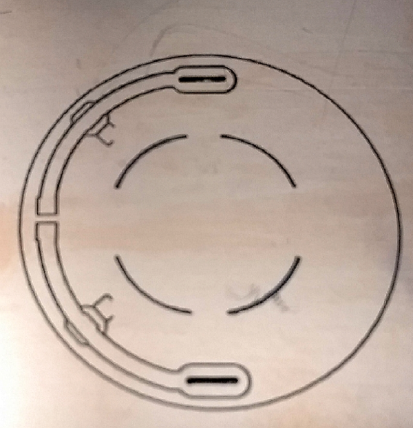 | This operation uses a 0.6 mm, 2-flute flat end mill, to mill theslots that allow the PCB to fit over the motor power tabs. With this bit installed, the Z axis is re-zeroed so that the mill is touching the surface before starting. The Height Map is alsobeing used. 3-passes are used in this operation so that stresses on the mill are minimized. Each pass uses a cutting depth of 0.6 mm. |
3MNS-Through.drl_mill14mmhole_1.0mmCutter_cnc.nc | 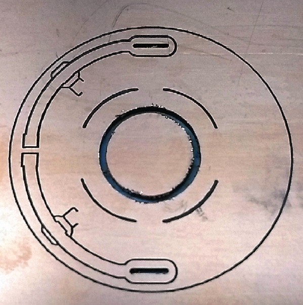 | The third operation uses a 1.0 mm, 2-flute flat end mill to mill thenominal 14 mm hole in the center of the PCB, so that it can fit over the motor bearing hub when mounted. As before, with this bit installed, the Z axis is re-zeroed so that the mill is touching the surface before starting. The Height Map is also being used. 3-passes are used in this operation so that stresses on the mill are minimized. As before, each pass uses a cutting depth of 0.6 mm. |
4MNS-BoardOutline.gbr_ext_mil_1.5mmCutterl_cnc.nc | 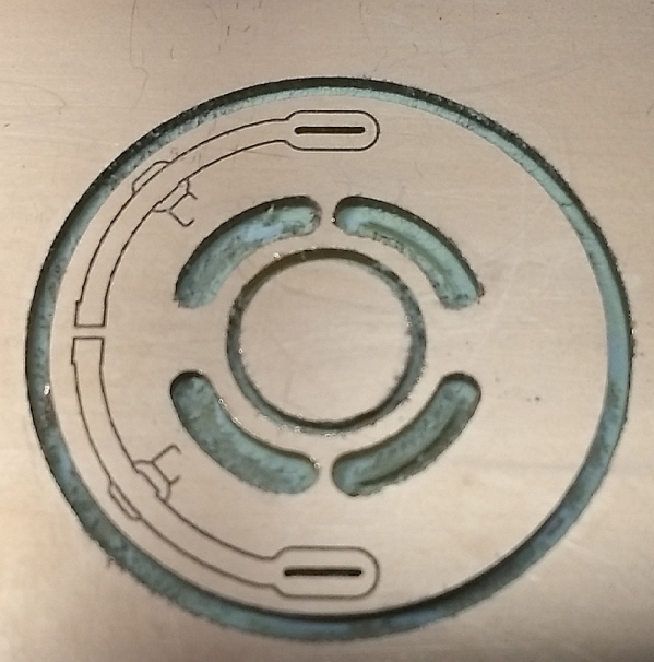 | The last milling operation performs a perimeter cut and mills out the cooling slots. All of this is done with a 1.5 mm, 2-flute flat end mill. As before, with this bit installed, the Z axis is re-zeroed so that the mill is touching the surface before starting. The Height Map is also being used. 3-passes are used in this operation so that stresses on the mill are minimized. As before, each pass uses a cutting depth of 0.6 mm. |
Post-Processing Your PCB
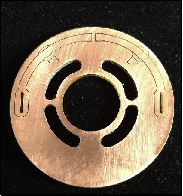
After removing the PCB from the CNC machine, it is ready for further work. A light sanding under running water with 350 to 500 grit wet or dry sandpaper is a good way of removing any copper threads that might still remain from the milling operations. In general, the PCB should look like the image below.

The last check to perform is to look at the back side of the PCB, with a bright light shining through, to see that the isolation milling was deep enough to remove enough copper that the tracesare indeed isolated from each other and the ground plane. The image to the left is an example of what it should look like.
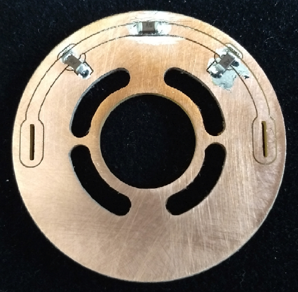
With the capacitors soldered to the PCB, it looks like this:
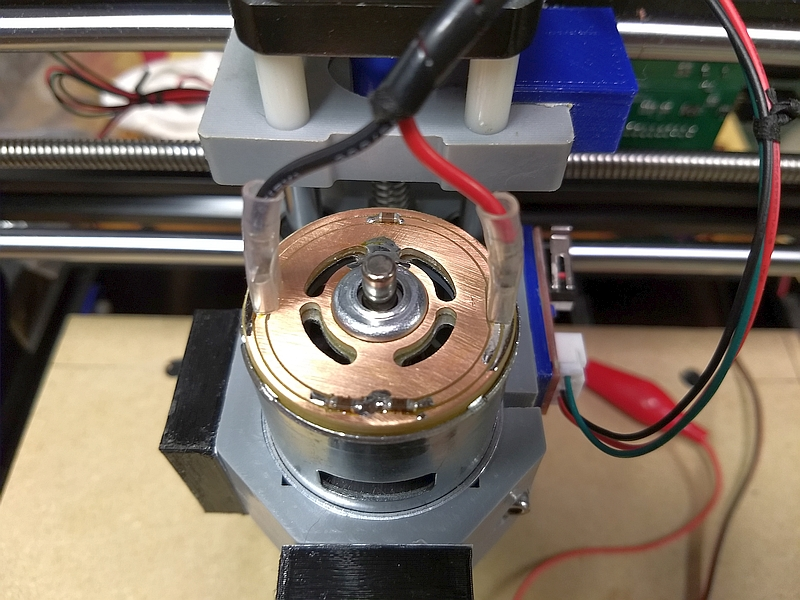
The final step is to solder the PCB to the back of the motor. This final photo shows that step, with an earlier version of the PCB, installed on my SainSmart 3018 Pro.