Fusion 360 Quick-Start Guide for 3018 Pro & PROver CNC’s
 Updated
The items you may need:
- SainSmart Genmitsu CNC Router 3018-PRO DIY Kit
- SainSmart Genmitsu CNC Router 3018-PROVer Kit
- Download Fusion 360
Step1: Setting Up Your CAM Workspace
Just like you have to set the table before you have dinner, so do you need to set up a workspace in Fusion 360 in order for your machine to know what you want it to do. The first step in this process is (with your model visible) to go from the “ Design ” to “Manufacturing” tab in the top-left corner of the program.
As you do so, you will see the interface change. It is wise to think of each of those tabs as separate programs, with Design being for CAD (Computer Aided Design) purposes while the Manufacturing tab is CAM (Computer Aided Manufacturing). The First focuses on making 3D models, while the second is meant to help turn a digital model into a real physical product.
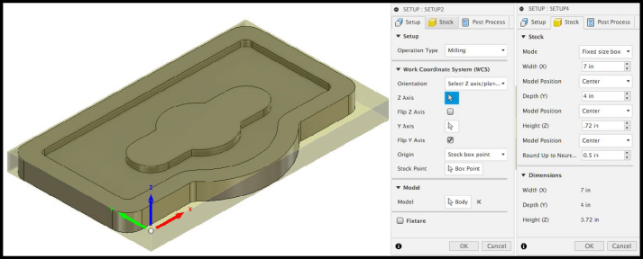
Directly to the right of the Manufacturing tab is the Setup button, start by clicking it and the above menu should pop up. You will see a translucent box show up around your model, this represents the stock material that you will be placing in your Machine.
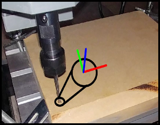
The most important part of the setup process is figuring out where your Work Coordinate System (WCS) will start from. For the most part just think of this as where the bit will be placed before you tell your machine to start cutting. For ease of use, many people select the bottom left corner like the above, and you want to make sure that the blue Z arrow is pointing upwards, and that X & Y are hugging your work piece.
Once your project looks like the above you can go to the Stock tab and modify the dimensions of the stock material. Under the Mode selection, I suggest using “Fixed Size Box” to fully define your stock materials. In this case, we already know the Z height (.72” on Z Axis) from our measurements earlier, and now you can measure your stock’s length (4” on Y Axis) and width (7” on X Axis).
With your WCS looking like the above image and your stock dimensions set, you can select ok and move on to creating toolpaths.
Step 2: Generating The Pocket Operation
To start making your cut around 2D parts, go to the “2D” drop-down menu and select the “2D Pocket” operation. From there, you will need to enter the parameters to define the cut, which are listed in a tab format just like the Setup. First, in the “Tool” tab, click on “Select tool…” and pick a 1/8” end mill from one of the stock libraries, or make a new tool yourself.
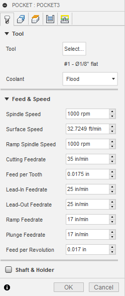
In the first tab, after you have selected your end mill, you will need to alter all of the feeds and speeds settings based on a variety of factors. There are a lot of features you can modify, enable or disable but for the sake of this quickstart guide we will focus on the essentials:
- Spindle Speed & Ramp Spindle Speed: For the sake of simplicity, make a habit of setting both of these settings equal to one another. As one might expect, this setting dictates how fast your spindle will turn, but setting it to 1000 does not equate to 1000 RPM, but rather is relative to the $30 value in your GRBL settings. So 1000 = Max speed and 500 = half speed. Anything over that $30 value just defaults to Max Speed.
- Cutting Feedrate: This is the primary value used to dictate how fast your CNC tries to slice through your project. This value varies wildly depending on how deep you are cutting per pass. The deeper you cut, the slower you have to set this.
- Lead/Ramp/Plunge Feedrate: These settings dictate cutting feedrate through various more stressful movements your machine might make. These should always be lower than your cutting feedrate. Generally for Lead-In/Lead-Out, 10-30% slower is a good setting to test at, and 30-50% slower for Plunge/Ramp feedrate.
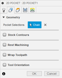
In the second tab (seen to the left) you need to select the pockets that you want to be cut out. For this example, only one is cut, but you could select as many as you want per operation. Take care to select carefully so that nothing is cut that you do not want to be.
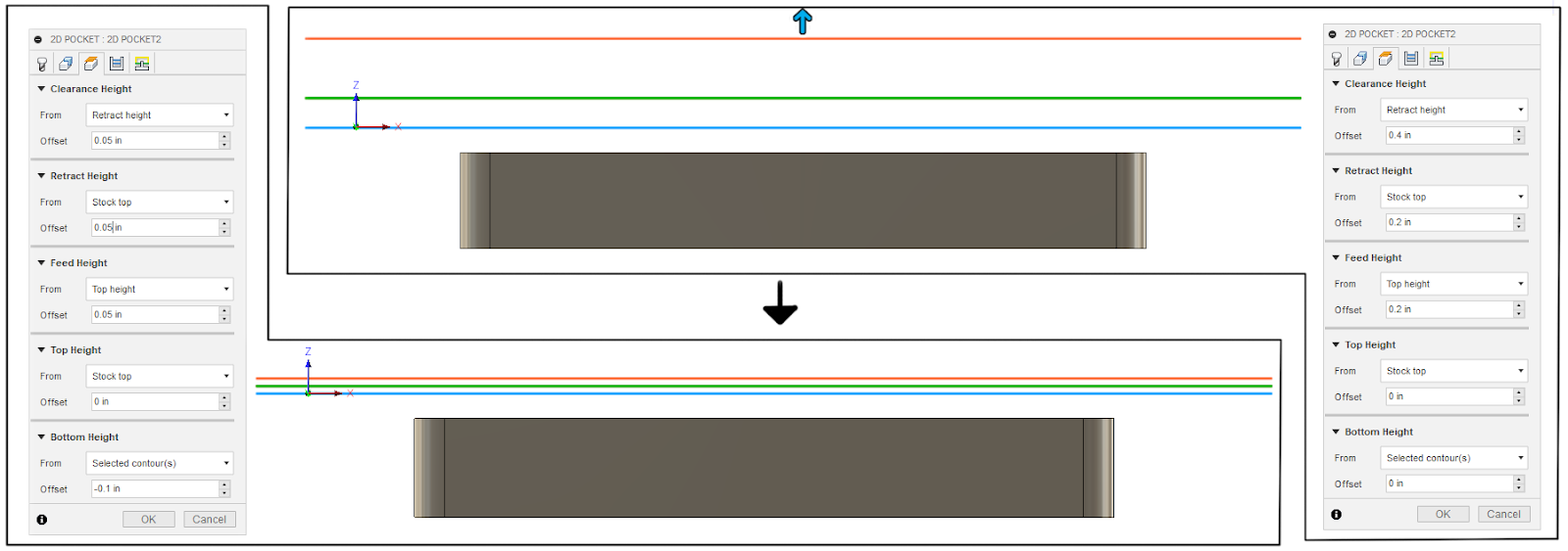
The third tab deals with clearance heights, or more simply, how much space to maneuver your CNC has. The default settings for Autodesk Fusion 360 are pretty conservative for most CNC’s on the market, but for desktop models like the Pro and PROVer, some further adjustment is needed. In the image below, you can see how everything was set initially in the top-right, as well as how they were modified in the bottom-left. Essentially though, the changes made were to decrease Z movements to be more compact and keep it closer to the stock material.
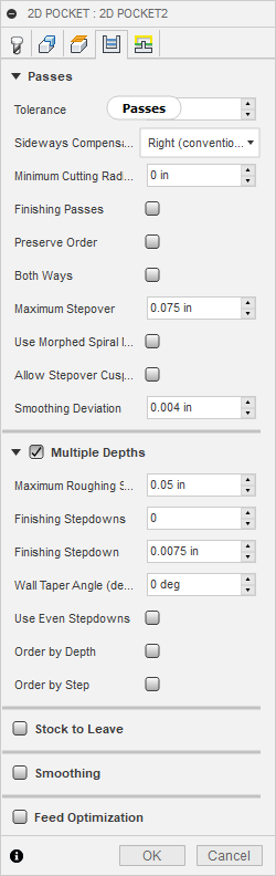
In the 4th tab, shown to the right, you have settings that dictate quite a lot of different options, but it’s easier of to thing of this tab as handling primarily the depth of cut, stopover, sideways compensation and stock to leave:
- Maximum Stepover: This should be no larger than 90% the diameter of the bit you are using, more likely much less. The lower the number, the longer it will take to cut, but the less the CNC will struggle and the better it will look; It’s a tradeoff.
- Multiple Depths: Always enable this for every operation you can, it is disabled by default. Under Maximum Roughing Step Down, you will set how deep each pass will cut until reaching the final destination. More often than not you will need to do quite a number of passes.
- Stock to Leave: If you enable this, extra material will be leftover that you will need to create another operation to clean up. The extra effort is worth it though, giving you a cleaner finish; For this operation it is left disabled.
- Sideways Compensation: Always use Right (Conventional), as it is more reliable.
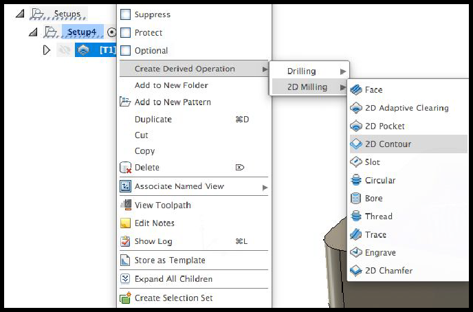
Step 3: Generate The Contour Operation
In order to save us some time, right click your Pocket Operation and create a derived Contour Operation. This will import many of the settings that you changed last time, such as bit selection, cut depth, feeds & speeds and the like.
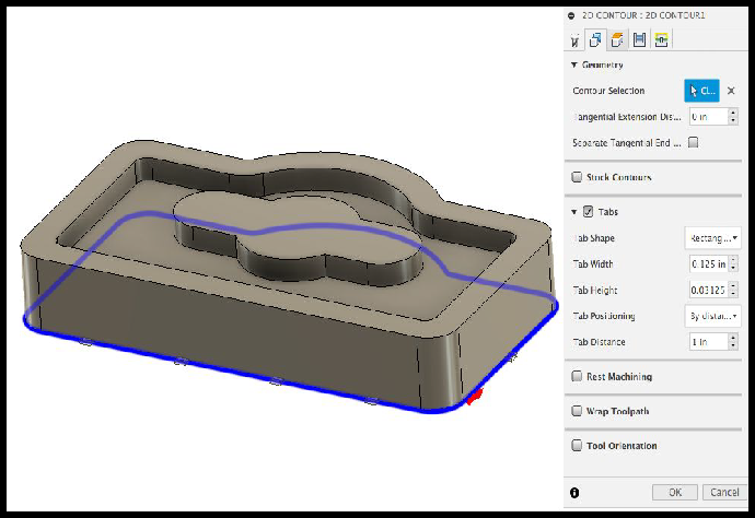
The only things you need to change are in the geometry tab of the new 2D Contour Operation.
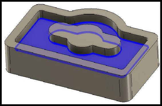
First you need to change your contour selection to the bottom, outside edge like shown to the left. This operation is meant to cut your project free from the rest of the stock.
The other thing you need to change is enabling “Tabs” which will automatically generate small bridges between the stock and the part being cut out that can be easily cut away later by a saw or other instrument. This is important because it all keeps the cut out part from moving around while the CNC is active.
Step 4: Saving & Exporting Toolpaths
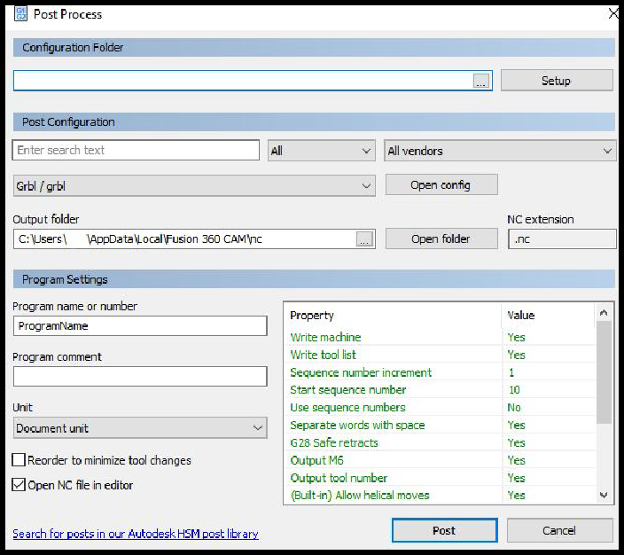
Assuming you are using the same bit for all operations, hold Shift while selecting all operations (making sure they are listed in the order you want them executed) and then find the “Post Processing” button in the toolbar; It looks like a big “G1 G2.”
The menu to the right will show up. You’ll want to select “Gbrl/gbrl” from the list to the left of the “Open Config” button, and then:
- Set Output M6 & Output Tool Number to NO
Select Post. This saves the file somewhere accessible with a relevant name.nc.
Step 5: Running The Toolpath
At this point, you have your .NC file, All you have to do from this point is open the file you made in the control software of your choice, zeroing the X, Y & Z work coordinates to match how it looks in Step 1, as shown below:
We suggest using Candle for this step, another free software package which can be used to operate your CNC and run toolpaths from Fusion 360 and other programs. For further information, consider reading through this guide on How to Set Up & Use Candle for Multiple Operations.