How to Install Your 4th Axis and Square it on the 4040 CNC

Introduction
On pages 6-9 of the user manual, instructions are given on how to install and align the 4th axis on your 4040 CNC, but the process therein requires precision instruments such as a dial indicator or a miscelaneous pin to be installed in place of an endmill. The purpose of this guide is to provide users with a more practical approach, requiring more basic or cheap tools.
Suggested tool:
- Digital Caliper (preferable) or a standard tape measurer
- 1/8" Shank, Flat Nose endmill, or any non-tapered endmill which can provide a flat edge
The great thing about both of the above suggestions is that they are both extremely useful for day-to-day CNC operations. A caliper is a CNC operator's best friend, and a flat-nosed, 2-flute endmill is one of the best general-use options out there.
Squaring your X-Axis
Before you even get your rotary module out of the box, or after (either is fine), you will want to make sure that each side of the X-axis is squared to the frame. If it is crooked then the rotary module will get installed crooked as well. In order to check this, home your CNC. You will want to then use your caliper or tape measurer to compare the distance from the front for the left and right side.
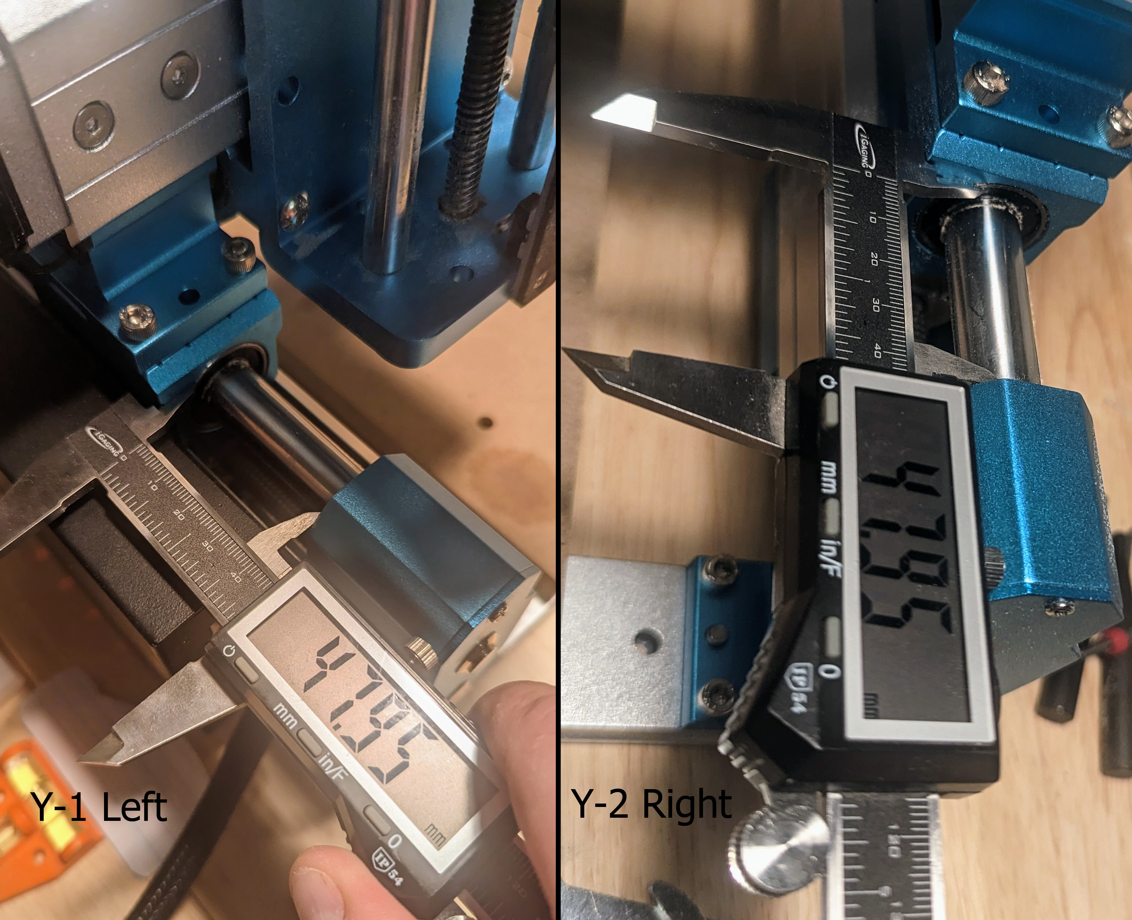
You will want to get the two measurements as equal as possible, regardless of what it is. This can be done by adjusting the knobs on your Y1 and Y2 stepper motors manually (by hand). Don't worry if the difference isn't exact, but the closer the better. Once you have each side equally spaced, try jogging the Y axis backwards by 100mm, and then home again. After doing so you can remeasure one last time.
Once you have it where you are comfortable, install the flat nose endmill into the spindle, and then jog the Y axis towards the back of the CNC to make room for installation.
Lower The Z axis assembly (Temporary)
Setting up your Z-Axis
As you may know, the 4040 Pro CNC has two different positions where you can install your Z axis (See page 13 of the CNC user manual). The two different mounting positions can be seen in this image:
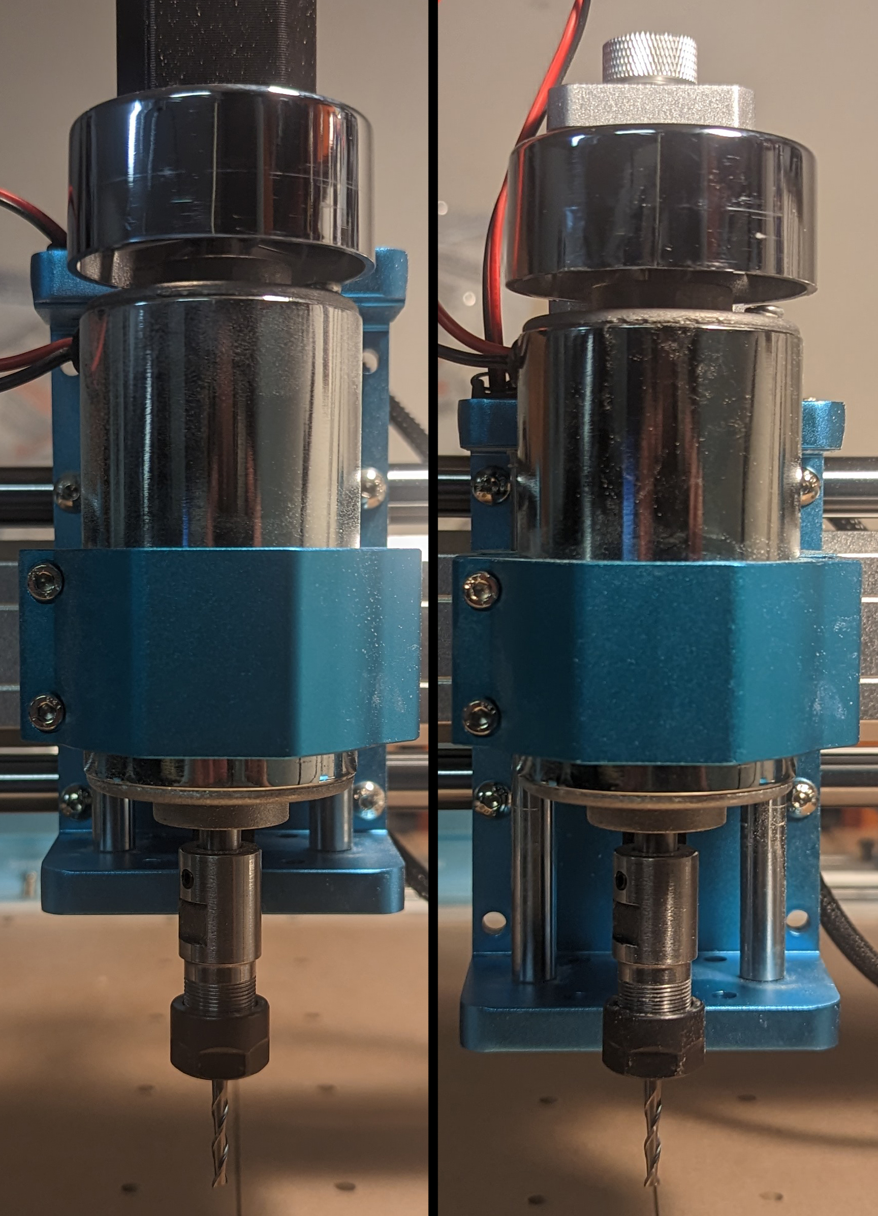
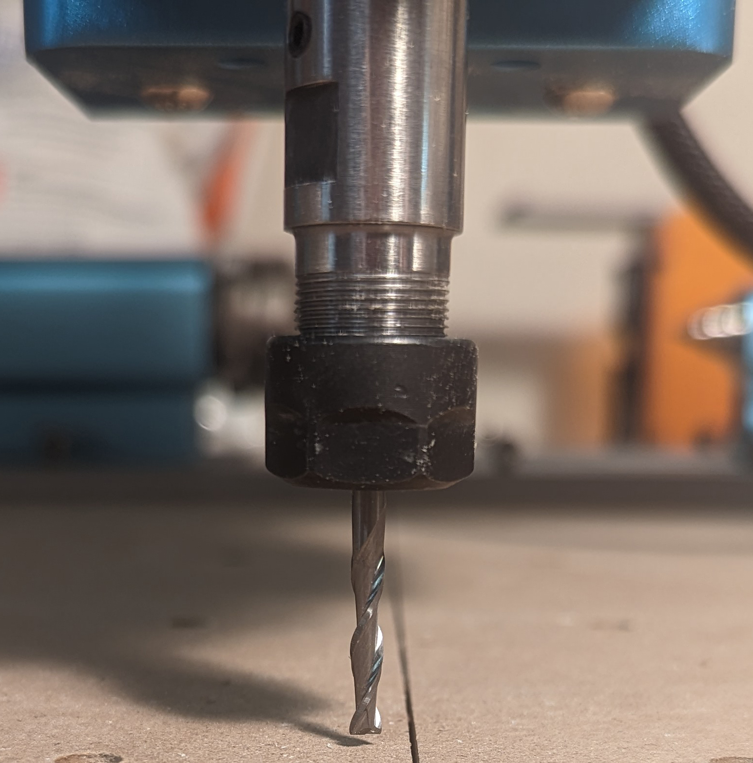
For the purposes of this guide, you will need the Z axis installed in the lower position unless you have an exceptionally long endmill. This is needed whether you have the stock 775 Spindle, or an upgraded 300w Spindle like the one used in the pictures above. The reason for this is that you will need your spindle to be able to reach a point just above (But not touching!) the spoilboard surface:
This will only be temporary, though. As soon as the 4th axis has been installed at the end of this guide, you will want to install the Z axis in the higher position.
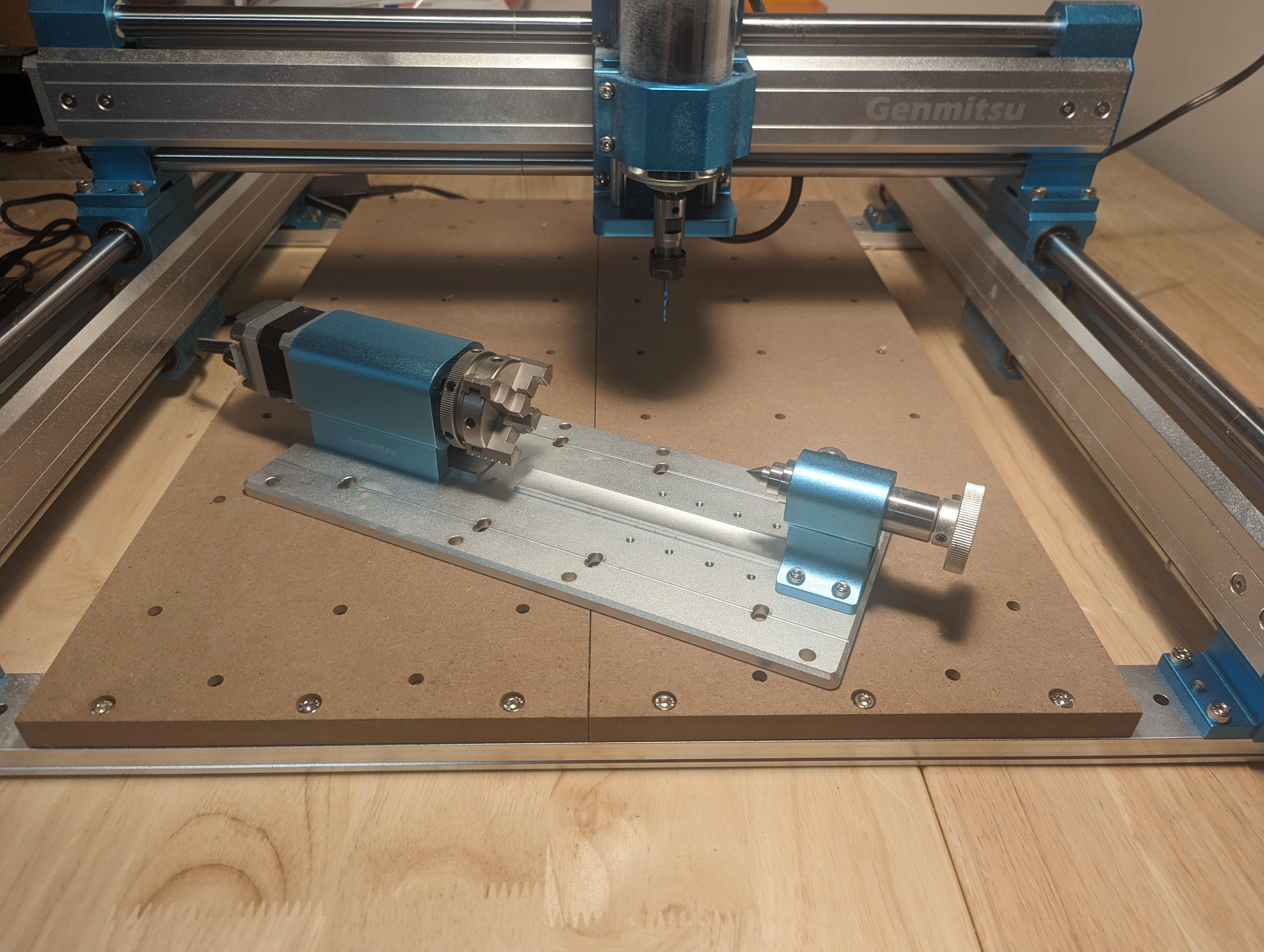
Installing the 4th Axis in Preparation for Squaring
Install the 4th axis as shown in the image below, taking care to screw in the bolts only very lightly, you should still have the ability to shift it forward and back with minimal resistance. This is super important; double and triple check it. If any of the 8 screws are too tight to prevent the spindle from pushing it into place as needed you can risk damaging or breaking your endmill.
With everything loosened, and the 4th axis roughly placed, push the 4th axis away from you so that it is shifted as far back as possible in order to set things up for the squaring process:
Squaring your 4th Axis
Wear Safety Glasses for the duration of this guide and unplug your spindle from any power sources just to be abundantly safe. Your Spindle should not be powered!
The process of squaring your 4th axis will involve lowering your spindle so that the endmill is just above the surface of the spoil board without touching it. You will then want to jog your X and Y axis so that it is close to the rear-right corner of the base of the 4th axis. Set your jog to a slower rate and jog the Y axis towards the front of the CNC until it pushes that corner of the 4th axis slightly.
Be very careful not to push too much, if you do jog forward too much, you will force the 4th axis against the screw, ruining the squaring process and potentially breaking your endmill.
Once the corner is pushed, tighten the closest screw so that the right side of the 4th axis will not shift, and then jog the X axis to the left until you clear the 4th axis. Follow this by tightening all screws fully. Here is a video of the process for reference:
For best results, make sure that your endmill does not rotate while jogging the X-axis, as this will provide less accurate placement. If the endmill rotates we suggest starting over from the previous step of moving the Y axis back and away followed by pushing your 4th axis towards the back again.
Congraduations, your 4th axis is now Square and ready for engraving. Make sure to reinstall the Z axis in the higher position and you are good to go!