Introduction to CNC for a Total Novice: Setting up a Laser
 Updated
The items you may need:
The laser module for 3018PROVer and 3018PROVer Mach3
Introduction
This guide is a part of the “Introduction to CNC for a Total Novice” series. Along with the guide itself, to utilize this resource successfully you will need the accompanying files, which you can download together as a .zip file. The files included are as follows:
Files Name | Description |
GBCustomButtons.gz | A custom button setup for easier use of LaserGRBL, including all the coding, icons and setup. Just import into LaserGRBL. |
TracingTest GCode-V2.xlsx | Excel spreadsheet which generates simple GCode for some setup tests, mainly for a Laser. It allows you to easily change the speed, feed with other parameters. Draws vertical lines, an array of boxes with varying speeds and feeds, a focusing test and a more complex shape to determine the effect of acceleration rates. If you don’t have Microsoft Excel sample GCode files are provided which of course can be edited using a text editor. |
LaserDrawLines.nc | Laser Draws/cuts/engraves 10 vertical lines, settings are in comments at the start of the .nc file. |
LaserDrawBoxes.nc | Laser Draws/cuts/engraves 5 rows of 10 boxes, settings are in comments at the start of the .nc file. |
LaserFocusTest.nc | Laser Draws 11 vertical lines above a set of reference marks. The Z axis is varied between each line with the centre line being at Z0. A set of reference marks at a higher power are drawn first to show where each line should be. If the laser focus is exact the centre line should be perfect, the ones to the sides, less perfect. Settings are in comments at the start of the .nc file. |
LaserAccelerationTest-30.nc | Draws a more complex shape designed to determine the effect of increasing the $120-122 acceleration values when using a laser. Acceleration values set to 30mm/sec/sec |
LaserAccelerationTest-1000.nc | As above but with acceleration set to 1000mm/sec/sec |
LaserAccelerationTest-5000.nc | As above but with acceleration set to 5000mm/sec/sec |
SpindleAccelerationTest-30.nc | Draws a more complex shape designed to determine the effect of increasing the $120-122 acceleration values when using a Spindle Motor. Acceleration values set to 30mm/sec/sec |
SpindleAccelerationTest-1000.nc | As above but with acceleration set to 1000mm/sec/sec |
SpindleAccelerationTest-5000.nc | As above but with acceleration set to 5000mm/sec/sec |
Safety Precautions
Even the weakest of laser modules is strong enough to destroy your vision completely, and that of any pets, children, or spectators. With weaker lasers, like a portable laser pointer, usually it needs to be projected directly into the eye to be damaging, but with laser engravers there is a risk of damage even from observing the laser indirectly (such as engraving a project) if everyone present is not wearing proper eyewear.
For this reason, a pair of safety goggles is included with the purchase of a 2.5W or 5.5W laser. They are designed to limit the frequency of the light which can pass to prevent any damage and tend to be specific to particular lasers which use different wavelengths of light, the supplied goggles are designed for use with these lasers which use around 450nm as the wavelength. If you use a different laser then you will need something suitable for the frequency of that laser.
If cutting a flammable material, for example paper, it is quite possible to set it on fire. If cutting a material such as MDF from which the dust can be toxic, and when burnt the fumes are also toxic. Hitting a resin pocket in a piece of pine can cause a fire. Because of the above, only operate your laser in a well ventilated area, wearing a face mask to protect from fumes and the supplied goggles to protect your eyes. It is also wise to take note of the location of the nearest fire extinguisher.
Mounting The Laser Module
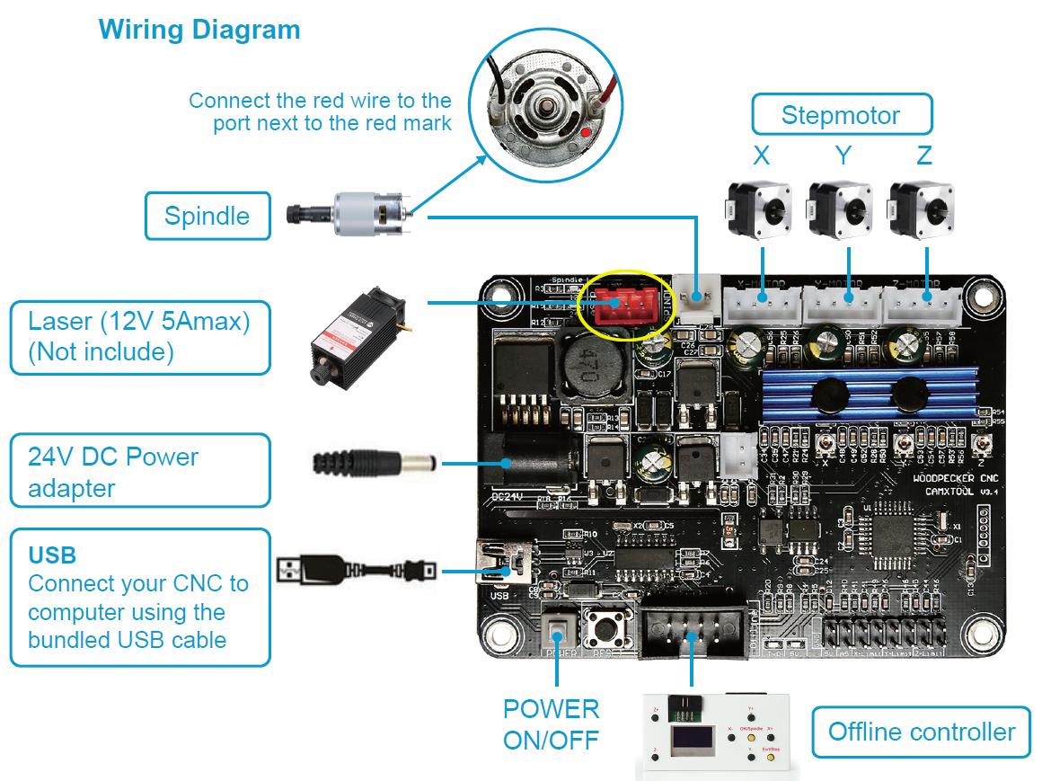
With the Cooling fan pointing up and away from your machine, fit it squarely into the grooves in the spindle mount and secure into place. Follow Connection Diagram A from this PDF to connect to CNC if you are using a PROVer CNC. Please note, that while the attached diagram used is for the MX3 board, the pin locations are identical to those on the PROVer board.
Follow Connection Diagram B from the above PDF if you are using a 3018 Pro CNC. While the the 3018 laser port location is different, the wiring diagram remains the same. To locate the laser port, please see the circled red port below:
Focusing The Laser
The laser unit has a knurled adjustment knob at the bottom, this screws onto a threaded shaft which contains the focussing lenses. The shaft is prevented from (easily) slipping by a spring mounted inside the laser which keeps some pressure on the shaft threads. By rotating the knob in different directions, you can bring the laser in and out of focus relative to a given surface, and keep in mind that you will need to re-focus the laser for each and every project.
Alternatively, if for some reason you are having issues focusing the laser with the knurled adjustment knob, you can also raise or lower the Z axis on your CNC towards the same effect.
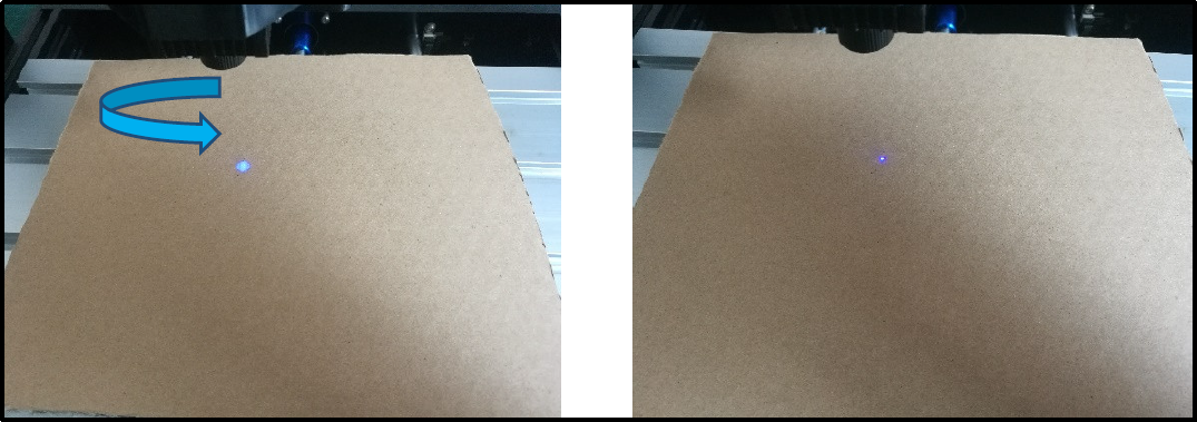
As seen below, you essentially want to make the laser point on your project as small as is possible.
Setting Up LaserGBRL
LaserGBRL is a free, laser specific controller for your CNC. It is capable of loading GCode, image files, both pictures and vector graphics and generating GCode optimised for laser engraving and cutting from them. You can find a quick overview of the LaserGRBL main window, as well as tutorials and details available on the website. Look here for more details.
Out of the box LaserGRBL does not have any jog buttons for the Z axis shown. But this can be enabled by going into the settings window, selecting the Jog Control tab and check Show Z up/down control. Then save. Now you should see at the right of the Jog controls a set of Z axis control buttons allowing coarse and fine movement of the Z axis. The set Zero Point button (the globe) sets zero for all axes. Use of these buttons is the only time LaserGRBL will move the Z axis. (Unless you are loading GCode files which move it.)
Adding Custom Buttons
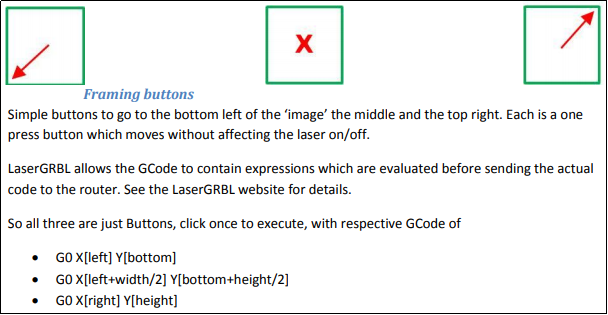
LaserGRBL allows you to add custom buttons to the bottom button bar, after the lightning bolt, padlock and globe. What these do is send GCode or setup commands to the router. Read here for background.
To add more functionality, included in the associated files is one called “GBCustomButtons.gz” which you can import directly into LaserGRBL by right clicking in the custom button area, select Import custom Buttons and select the GBCustomButtons.gz file. You will have to confirm each button so just click yes to all the pop-up windows. The buttons add the following functionality:
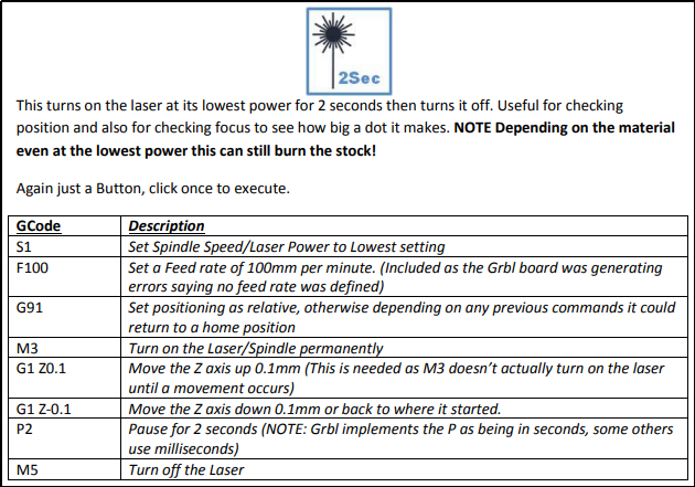
Focus Point
To cut or engrave efficiently we want the laser beam to be tightly focussed into the smallest possible point at the top of the stock. This depends on the distance from the laser emitter to the spot and is controlled by the position of the focusing lens as adjusted by the focusing knob.
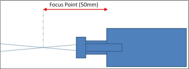
The focal length is the distance from the lens to the point where the beam of light becomes a very fine dot and then expands again. For the sake of practicality, consider 50mm from the bottom of the laser heatsink, as shown above, to your focus point.
How To Focus
It helps, and makes it easier to repeat if you have a 50mm guide to quickly bring the laser into focus. This could be something you CNC’ed or even just a plastic drinking straw measured and cut to length. Using the Z axis jog controls and a ruler (or your guide piece) position the bottom of the laser heat sink 50mm above the top of the stock.
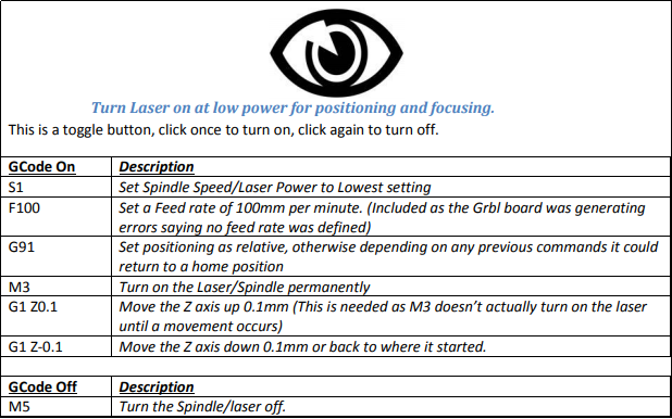
Now at that position, use the custom button in LaserGRBL to turn on the Laser at low power Rotate the focussing knob until the centre of the laser ‘colour’ is a tightly defined dot. Make sure to keep your fingers away from the path of the laser during this process.
What you will see is a blob within a much wider shape, depending on the laser. The aim is to make the brightest part of the blob in the middle as small and as bright as possible. If you are using a burnable material as your stock and the laser starts to burn through, turn it off, move the beam a few mm or so left or right and repeat. This is so you are still measuring the focussing point measured at the top of the stock.
Testing The Focus
In the accompanying files there one labeled “LaserFocusTest.nc.”
This is a simple GCode file which first cuts 11 markers just to show where the lines should be, then cuts 11 lines. BUT when cutting the lines the Z axis is first moved down 5mm and moved up by 1mm between each line starting on the left. So at the left the focus is 5mm out, too close and at the right is 5mm out, too far away.
If everything is perfect then the resulting lines should be symmetrical about the middle and the one in the centre should be the best. If not adjust the focus a little bit, move the paper to a new position or jog the laser and try again. Please note that depending on the position of your laser module in the spindle mount, there might not be the needed.

5mm of movement for this test. If this is the case, untighten the mounts grip on the laser and move the module down so that it is sticking further out than it was before. Tighten it back up and find the focal point again. You should eventually get something like this:
This is a good illustration of the importance of correctly focusing your machine. As you can see, the outer lines which are +/- 5mm and 4mm don’t even scorch the paper, 3 and 2mm aren’t great, -1 to +1 seem OK. This obviously depends on the stock, feed and speed you are using. If your ‘good’ lines are off to the left then your focussing point is too far out so screw the focussing knob in a bit, if they are to the right screw it out a bit then retry.
It is worth noting that If you turn the laser up to max power and a low feed rate for this test, you will probably see all of the lines. This entirely defeats the purpose. As such, adjust the feed and speed accordingly until at least the outer lines do not show up.
Focus Adjustment Troubleshooting
Problem | Possible Solution |
Focus doesn’t seem to change. | Check the end cap at the end of the threaded shaft is secure. The focus is changed by moving the threaded shaft in and out of the laser body, moving the cap by itself has no effect. |
Focus is set but it stops cutting on parts of the stock. | If you haven’t already then attach and level a Spoilboard and make sure that the top of your stock is level. You can test this by re measuring the distance from the stock top to the laser at different points. |
I cannot see the dot easily when focussing. | Use something semi reflectable like a piece of steel or aluminum foil to focus on. |
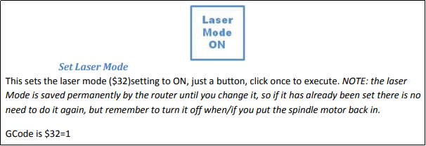
Laser Mode
Grbl has a setting for Laser Mode, $32, $32=1 sets Laser Mode, $32=0 sets it off. This changes the behaviour of the router slightly; the laser or spindle will still work regardless of the setting. The major change is that it will be turned off during positioning moves. So if you see lines being drawn where you don’t want them, when the router is just changing position your laser mode is probably off!
A Spindle motor with a collet and bit attached is a mechanical rotating device and is subject to the laws of physics concerning angular momentum, gyroscopic effects etc; if you change the spindle speed from 500 to 1000 it will take a little time to reach the new rotational speed and if the other way round a little time to slow down. The router motherboard compensates for this by waiting in the same position for a little time to allow the speed to change. Even if it is in the middle of a cut it will stay in the same place momentarily which shouldn’t make a difference to the cut.
A laser's power is not subject to the laws of momentum, setting the power from S500 to S1000 happens instantaneously so probably the last thing you want is for it to stay in the same place for a moment, still burning at the new power setting before it starts moving again.
So when you put in the laser module send a $32=1 to the router, if you have modified LaserGRBL just click the Set Laser Mode Custom button. When you put the spindle motor back send a $32=0 to the router. This only needs to be done once each time you change between the laser and the spindle motor, at the start of each job is unnecessary. The sample GCode files provided all set the Laser Mode on at the top.
From the Grbl 1.1 release notes:
**Laser Mode** : The new "laser" mode will cause Grbl to move continuously through consecutive G1, G2, and G3 commands with spindle speed changes. When "laser" mode is disabled, Grbl will instead come to a stop to ensure a spindle comes up to speed properly. Spindle speed overrides also work with laser mode so you can tweak the laser power, if you need to during the job. Switch between "laser" mode and "normal" mode via a `$` setting.
**Dynamic Laser Power Scaling with Speed** : If your machine has low accelerations, Grbl will automagically scale the laser power based on how fast Grbl is traveling, so you won't have burnt corners when your CNC has to make a turn! Enabled by the `M4` spindle CCW command when laser mode is enabled!
Further Testing
For these next tests, the plan is to use the file labeled “LaserDrawBoxes.nc”to test variable sizes, spacing, speeds and feeds. It is useful to see what difference they make and to try and break down the best areas to explore further and ultimately try and determine the range of values that produce the best results and to see the effects of using different materials.
It is a good idea to get in the habit of performing a similar test whenever you try to cut or engrave a new material. Results will vary wildly between two different materials of similar nature, such as the different color papers used below.
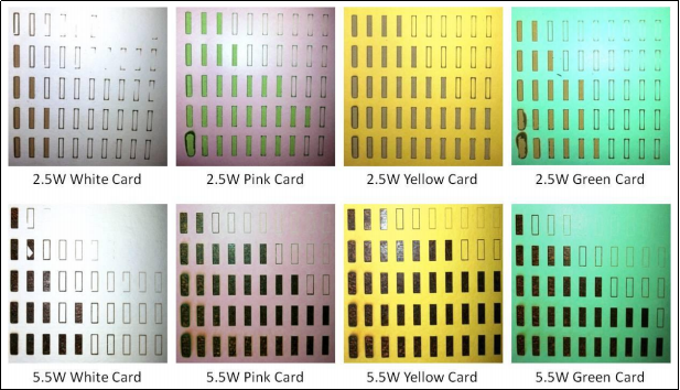
As shown, unless you have exactly the same card and paper as was used, your results will be different, but as something to show how the material used affects things, quite useful I think. This is meant to give a starting position, from which further fine tuning will be needed depending on a given material.
Some rough conclusions, then:
- Very slow speeds at high power are bad, leaving the paper burning and making thick lines.
- High feed rates and low power are also bad as they will barely scorch the paper if at all.
- The material used, its colour, being shiny, it all makes a difference.
- If at all possible, for work with the laser, it is better to use non-flammable materials for your spoilboard.
Maintenance
Little is needed, but as the processes of using the laser will generate smoke and soot, it is a good idea every so often to clean the outside of the focussing lens, using a cotton swab dampened with window cleaner, then use the other end to polish it dry. Repeat until the cotton bud comes out clean.
Tidying up the lines
From Grbl Configuration Page: Finally, tune your settings to get close to your desired or max performance...... Tweak your $12x acceleration and $11x max rate settings to improve performance. Set to no greater than 80% of absolute max to account for inertia, cutting forces, and motor torque reductions with speed.
During the course of testing using the methods above, you might notice (depending on your settings) that the ends of lines are cut more heavily, ending in a thicker line followed by a burnt dot, some of the box tests engrave the corners but not the lines. This can be more finely tuned by tweaking your acceleration values.
$120, $121, $122 – [X,Y,Z] Acceleration, mm/sec2
These commands, $120, $121 & $122 sets the axes acceleration parameters in mm/second/second. Simply put, a lower value makes Grbl ease slower into motion, while a higher value yields tighter moves and reaches the desired feed rates much quicker. Much like the max rate setting, each axis has its own acceleration value and is independent of each other.
This means that a multi-axis motion will only accelerate as quickly as the lowest contributing axis can. Again, like the max rate setting, the simplest way to determine the values for this setting is to individually test each axis with slowly increasing values until the motor stalls. Then finalize your acceleration setting with a value 10-20% below this absolute max value. This should account for wear, friction, and mass inertia. It is highly recommended that you dry test some G-code programs with your new settings before committing to them. Sometimes the loading on your machine is different when moving in all axes together. The default values on most Sainsmart CNC machine are 30mm/sec/sec for all of them.
Consider this:
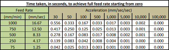
The above shows the effect of acceleration values on the time for the router to get up to speed depending on the feed rate assuming the spindle or laser is at rest to start with. So if you start a line from rest at a feed rate of 1000 it will take over a second before it is at full speed. With that being the case, it is no wonder the burn is heavier!
Grbl does include compensation for this when Laser mode is set, but could really do with further tweaking. These settings ONLY determine the acceleration of the spindle, letting the spindle reach its specified rotational speed is totally separate. Consider making an ‘air cut’ for a few mm before encountering the stock, the spindle would already be rotating at full speed and moving at the specified speed before encountering the stock. Remember the board could be trying to move a big spindle motor, for bigger machines.
Apart from how fast an axis can be accelerated by its stepper motor this should have no effect on anything else. It should be noted that unless you are only moving the spindle along in a single axis at a time the acceleration values on all the axes it is moving in will affect each other. Imagine a 45˚ movement on X and Y, the spindle can only be accelerated as fast as the lower of the X and Y accelerations to keep the line straight. One last thought is that the masses of the spindle and mounting, the bed+clamps and stock probably will be different so affecting the acceleration, just as on the Z axis when moving up has to lift the mass of the spindle motor and mount, going down should be easier.
Within the linked Zip file at the top of this guide, you can try out a number of different acceleration values and find the one that suits you best, but for those not looking to experiment, try setting $120-122 values to 5000 for nominal results.