DeskProto 4th Axis Software Guide

Introduction
In order to follow this guide you will need access to not just the base version of DeskProto, but the Multi-Axis edition specifically as well. If you are using this product as a hobby or for educational purposes, then you can purchase the Mult-axis edition for €248|$267. For commercial use, the same software is €995/$1071.
The If you want to follow along with the guide below, you can download the file for this project from this link and was cut out of this 1" wood dowl, cut down to fit into the 4th axis. As was the case with my dowel, it was neither 1" in reality nor perfectly round so it is very important to measure your stock material rather than copying my settings directly.
Also, make sure to take time and center/square your stock material properly. The process is covered for rounded stock in the latter half of this guide.
Step 1: Loading your File
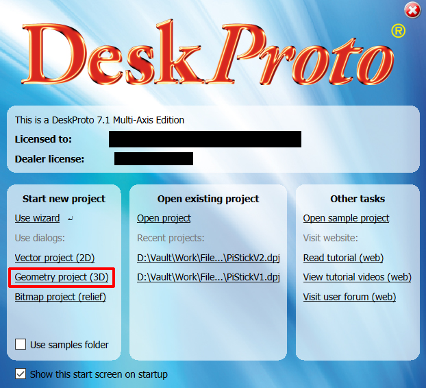
After selecting the "Multi-Axis Edition" upon startup of DeskProto, you will be taken to a new project wizard. Select Geometry Project (3D) and then open the STL file that you want to engrave.
Step 2: Endmill Selection
Before getting too deep into the rest of the process, it is best to start things off right by knowing what endmills you are planning to use for your project and adding them into the software. Once added they will stay permanent for later use, but more often than not you will need to add them in since the stock library is quite small. For this project, we will use one stock endmill, and one custom endmill.
Stock Endmill: Flat tip, radius 1/16 = diameter 1/8 inch
This one is already in the stock library and represents a more or less common 1/8" (3.175mm) endmill with two spiral flutes coming to a flat head/tip exactly like this one.
It is easy to misunderstand though, since DeskProto really likes using radius measurements instead of diameter. Even in the course of making this guide we accidentally selected "Flat tip, radius 1/8 = diameter 1/4 inch" which is not correct and things would not have gone well.
Custom Endmill: 3.175mm Shank, 2-Flute, Tapered Ball Nose Endmill with a .75mm Point.
In order to add a custom endmill, you will need to go into the Cutter Library, to get there find the Options drop-down menu and select Library of Cutters.
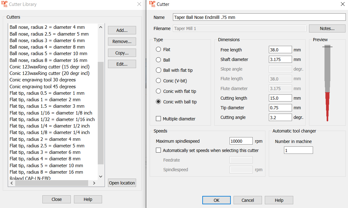
This will open up the menu on the left, where you can select to edit or add a new endmill. Once you select Add it will open the menu on the right and you can fill in all of the information. Where you get this information is through information from the manufacturer. In this case, the endmill being used is from this set. Sometimes the information is written out on the store page, but other times it is in one of the images like this one (which was the 3rd image on the store page).
Make sure to select the right type, and enter all of the information. The only information on this menu you won't get is the maximum RPM. We suggest setting it to 10000 to match the max RPM of your stock 4040 CNC spindle. Once the endmill is saved you can reference it for any future project.
Step 3: Project Parameters
Under the parameters drop-down menu, click "Project Parameters", and under the Machine option, scroll down and select GRBL (M) or GRBL (Inch) depending on your needs. This will be needed for any and all projects you do with DeskProto for one of our machines, 4 Axis or otherwise.
For this specific project, if you are following along, you will want to select GRBL (mm) then OK the selection and exit out of Project Parameters.
Step 4: Part Parameters
You can go to the Part Parameter settings by right-clicking your part file and selecting "Part Parameter" from the options shown. Alternatively, you can also go to the Parameter drop-down menu and select the same from there as well. This part of the guide will cover what parts you need for this project, but there are other features such as Ambient, Support, or Simulation you can explore as needed.
General Tab
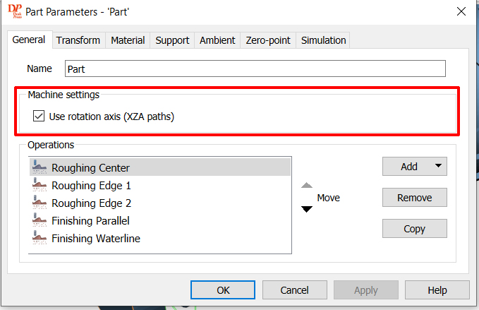
On the first tab, the General Tab, the only thing you need to worry about is making sure that "Use Rotation Axis (XZA Paths)" is selected. From there we can move to the second tab, Transform.
Transform Tab
The main goal in this tab is to enable "Center Geometry" but there is more that is needed on this page depending on the orientation of the model you import. This is your chance to change the size of your model, as well as rotate it to match the axis. For example if you import your model and the long end is along the Z axis then you would need to rotate it to point along the X axis.
Material Tab
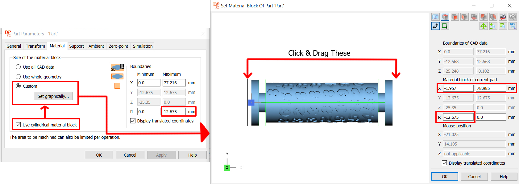
The material tab is where you will want to set the limits of your stock material. This can be handled in a few different ways but the way we suggest is to do the following:
- Under the Boundaries section, find the Maximum field for R and enter the radius (1/2 Diameter) of your stock material. Min can and should stay at Zero.
- Make sure to always measure your stock materials, and don't trust whatever the store told you it would be, those measurements are usually approximate. The 1" (25.4 mm) dowl that I got was not even round so measurements varied as I rotated the dowel around, so always measure a few times, and ideally close to wherever you willl zero your Z axis on the X plane.
- Select "Use Cylindrical Material Block" which is telling the software that your stock material is round.
- Select "Custom" Size of Material block and then select "Set Graphically" for the window on the right to pop up.
- In the graphic interface, you can click and drag with your mouse on each side of your model to set the limits where the CNC will and will not engrave. For demonstration purposes, I have pulled it away from the model on each side so that you can see it, but ideally, you want this to be fairly close to the model on each side, barring any special considerations.
- Once the boundaries are set, you can see the X-axis data on the left to get the full length of the stock material that you will need in the 4th axis and beyond the edges of the teeth in the chuck. So you need to make sure that your material is (in this case) over 81mm long, because your 4th axis chuck needs an additional 10+ mm to clamp on to.
- Hit OK on the Material Block window.
Zero-Point Tab
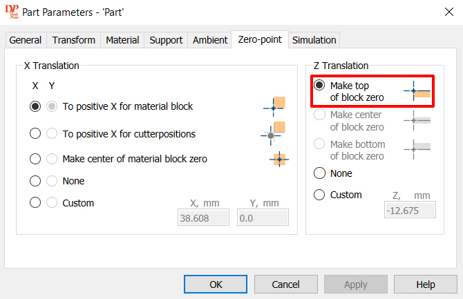
The only thing you would want to set here is the "Make Top of Block Zero" if it is not already selected. This makes sure that you will want to zero off of the top of your stock material just like you normally would with a 3-axis project.
With everything done, hit apply and OK.
Step 5: Geometry Operation Parameters
This section of the guide will cover toolpath settings and features that affect how hard and how fast the endmill of your CNC will engrave the stock material. It is important to understand that while the settings used for this guide do work and have been tested, this is by no means meant to be copied for any and all projects on the rotary axis. For your own projects, you will need to find what works for you on a case-by-case basis.
For this project, the General, Strategy, Roughing, and Area tabs will be covered.
You can get into the Geometry Operations Parameter menu by double-clicking the same under the Project Tree menu. Once you do it should open up with the General Tab.
General Tab
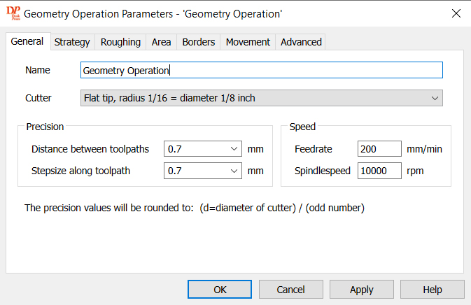
If you are planning to have multiple operations as you will see in this guide, then it is best to start off by naming this specific operation. From there you will need to select your endmill for this operation (See Step 2 for instructions on how to input new endmills).
From there you will go to the precision section. As a rule, these values should be no more than 1/2 the diameter of the tip that will be doing the cutting. Ideally, it should be much less than that for a better surface finish.
Under speed, you can set the spindle speed to whatever you need to based on the materials you are cutting, but the feed rate will be really, really important and totally subjective for your project. The settings above were used for the stock 1/8" diameter 2 spiral flutes flat endmill and worked quite well, but might be too slow or conservative for some users.
For those interested, the following settings were used for the 3.175mm Shank, 2-Flute, Tapered Ball Nose Endmill with a .75mm Point endmill:
Details
Feedrate = 300 mm/min
Spindle Speed = 10000
Strategy Tab
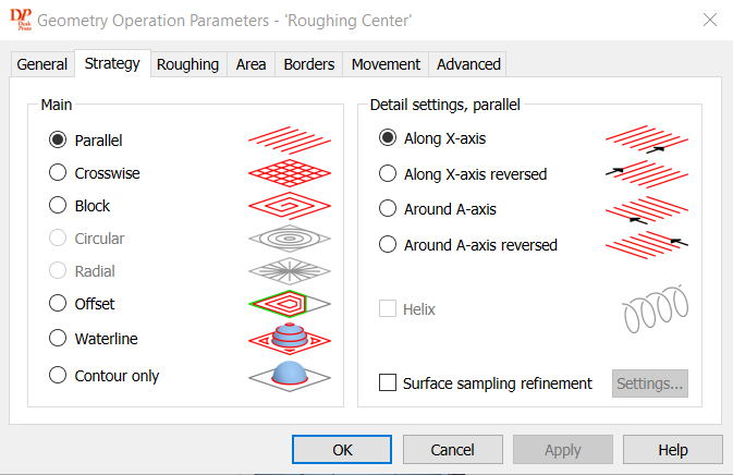
Things will be kept pretty simple for the sake of this guide but if you want to go into things more in-depth, see page 87 of the software reference manual.
For most purposes, a Parallel strategy running along the X or A axis (Both were used for this project to good effect) is all you will need, both for roughing and finishing passes with the separate endmills.
Roughing Tab
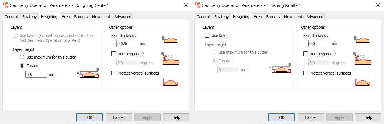
This tab, as the name implies is largely for roughing operations. Because of this, as you can see the settings for the roughing operation (using the flat endmill) and the finishing operation (using the conic ball nose endmill) are quite drastically different.
The reason for this is that when you do a roughing operation, there is usually stock material you need to shave away until you get to the desired dimensions of your project. In this case, under Layer Height, a value of .5mm was used, telling the CNC to shave away at the material .5mm at a time until the desired thickness was reached, with one exception.
That exception is the skin thickness. This tells the CNC to stop the X distance above whatever the desired surface depth is. This can be useful if you are going to do a finishing pass by leaving just a tiny amount of material left which the much finer endmill can cut through without struggling at all, leading to a much cleaner finish.
If you do not want to do a finishing pass, make sure the skin thickness is set to zero.
Area Tab
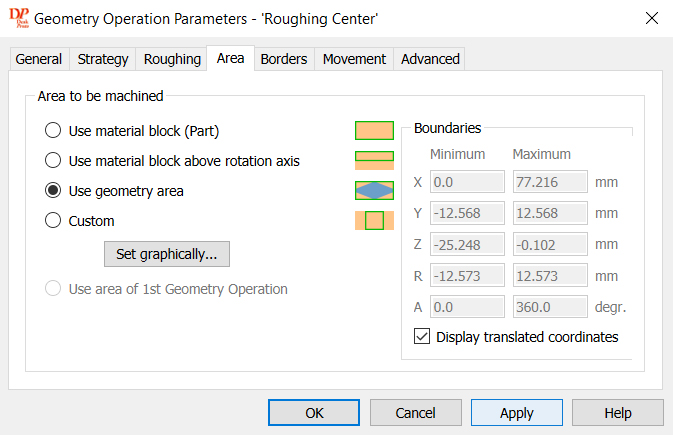
The area tab is very much like the Materials Tab from Part Parameters. The easiest choice is to use the geometry area, which will take the settings from that, or you can go into custom and set your own. This can be useful if you want to only engrave a part while leaving other portions out of it.
Separating the roughing operation into three different Operations (Left, Center, & Right) was done for this project, because after running the simulations (that will be covered) it was found that the interior edges were not cut fully because running a parallel path along the X axis did not cut fully in these areas. It could be changed to do the whole operation parallel along the A axis, but this takes a significantly longer amount of time. Instead, it was broken down to be as quick and accurate as possible:
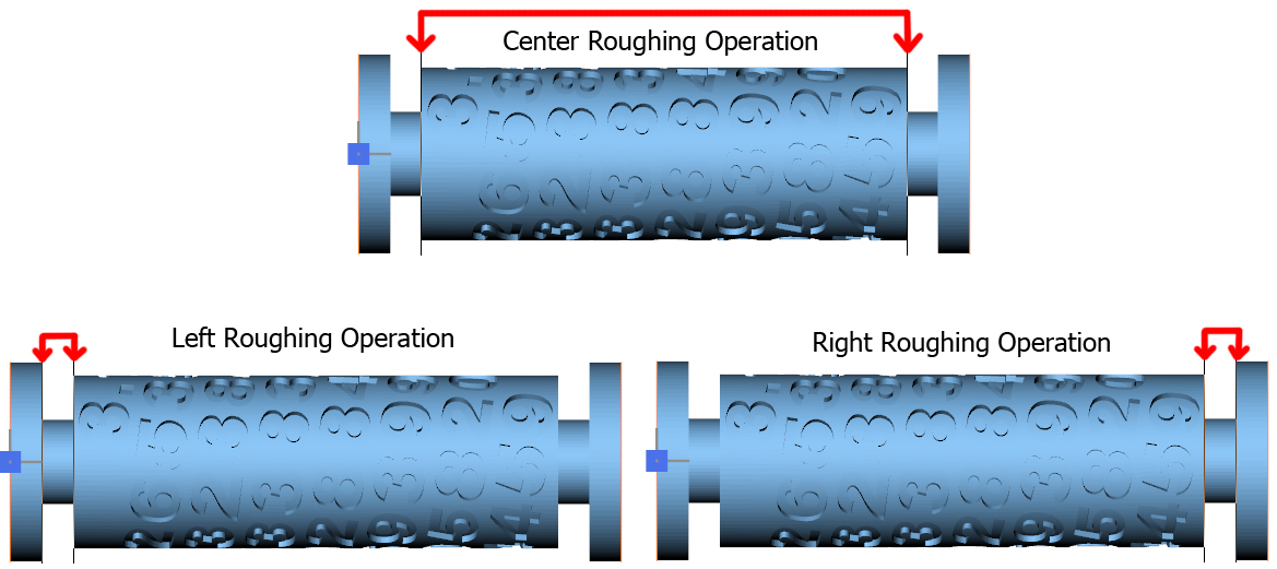
All three operations were identical save for the boundaries set, and which axis the CNC cut along. For the central operation it was cut along X, whereas for the Left & Right operation, it was cut along A. For ease of use, the first operation can be copied, and then that copy's boundaries altered thereafter by right-clicking the operation in the Project Tree Menu and selecting "Copy". Make sure to assign a new name right away to avoid confusion.
By the end of this process for both Roughing & Finishing operations, there was a total of 5 different Operations (3 Roughing & 2 Finishing).
Step 6: Calculate Toolpath
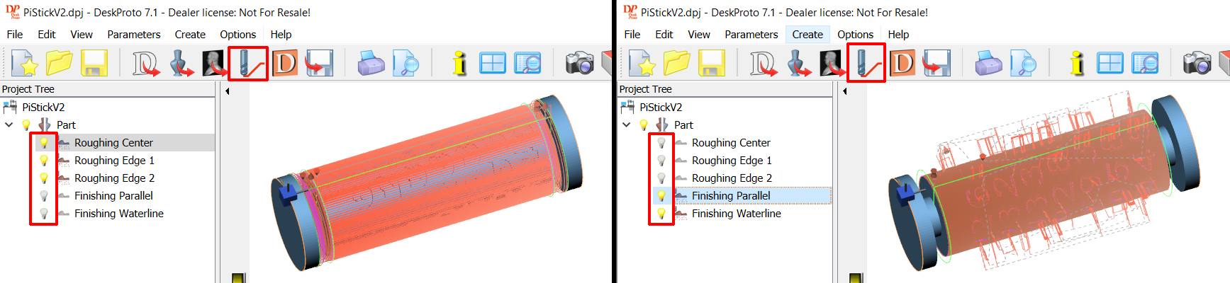
If you look at your project tree, you will see a number of lightbulbs, one for the part itself (don't touch that one) and one for each operation you made in Step #4. When you click on a lightbulb it will toggle between being On/Visible and Off/Invisible.
In order to calculate the toolpaths you will want to group things on and off by endmill type. In the Right example above we have the first three bulbs on because all three utilize the same flat-head roughing endmill, and the latter two use the conical ball-nose endmill.
With the lightbulb on for the roughing operation, you would then hit calculate toolpath, the button in the red box at the top. After this, you will see all of the simulated lines generated (it might take some time depending on how powerful your computer is). You can then turn off the 3 roughing operations, turn on the 2 finishing operations and do the same for those.
This can be done all at the same time, or one-by-one, but grouping by endmill will be super important for the next step so it is good to get in the habit.
Step 7: Generating & Exporting Gcode
Doing this is easy enough, all you have to do is click the floppy disk icon:
But what is not explicitly stated anywhere as you do this is that it will only export those operations that have lightbulbs that are On/Visible. You will want to group them by endmill, as discussed previously, so that your CNC will do all operations relating to that endmill from one file. So group the 3 roughing files, click the button, name the file, and save it somewhere you will remember.
Do the same for the 2 finishing operations and you are officially on your way to get things going on your CNC! If you are unsure what is involved with roughing and finishing operations on the practial CNC operation level, please take a look at this guide for more information. The guide only covers the X, Y, and Z axis, but thankfully At the end of a program, Deskproto instructs the A axis to return to where it started so you can avoid zeroing this out.
For further help continuing from this point see:
Files for Reference
- Base STL File (used to import to DeskProto)
- DeskProto Project FIle (Can be opened in DeskProto multi-axis edition to see everything as it was set up through this guide. This file can be modified to suit stock materials of other sized or make other adjustments as needed before exporting the new gcode)
- As-is Roughing Gcode File
- As-is Finishing Gcode File