Intro to CNC for a Total Novice: The Basics
 Updated
The items you may need:
- SainSmart Genmitsu CNC Router 3018-PRO DIY Kit
- SainSmart Genmitsu CNC Router 3018-PROVer Kit
- Download Candle for Windows
- Download Candle for Mac
- Download Fusion 360
Post-Assembly Quality Control
These are some simple checks to make once assembly is complete, but before you have zip tied or secured all the wiring, just in case you need to change any of it.
Are the axes connected correctly?
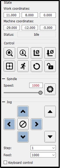
With your CNC powered on and plugged in, load up Candle and connect to your CNC if it does not do so automatically.
Set the step value in the jog commands area in Candle to 10 using the Step dropdown list, this sets how far the spindle will move in mm each time you click on a jog button, it needs to be something you can see but not move it so far it reaches the edges.
All movements on the axes are the spindle relative to the bed looking from the front. The left and right arrows should move the spindle left and right respectively, the X axis. Up and Down Buttons should move the bed forwards (the bed moves, not the spindle but the spindle gets closer to the top of the work), towards the front, or backwards, away from the front respectively, the Y axis. The two buttons on the right of the Jog commands should move the spindle height up and down respectively, the Z axis.
Troubleshooting:
Problem | Possible Solution |
The wrong axis moves | Check the connections from the stepper motors and make sure they are plugged into the correct X Y and Z axis connection on the router board. |
An axis does not move at all |
|
Does the spindle turn in the correct direction?
In the box above the jog commands set the spindle speed to 10 then click on the ‘Circular saw’ icon this should turn the spindle motor on and off. You should see it rotating in a clockwise direction. If this is not the case, then swap the wires connected to your spindle with the other.
Trying It Out
Mounting the Stock
Before letting the bit start spinning you will need some stock, a piece of something to cut. For the first attempt a piece of scrap wood is best, but for best results try to make sure that whatever you pick is fairly flat and level. You could use other materials but a bit of wood is cheapest and simplest. Your machine should have come with 4 clamps something like this:
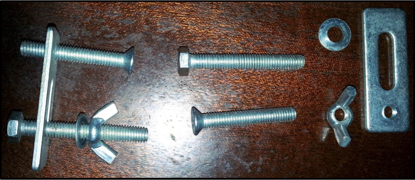
Put the pieces together so they transform into the one on the left. The head of the bolt slides into one of the slots on the bed, the screw is used to move the plate to be approximately horizontal when the end of the screw is on the bed and the top of the plate is on the stock. The wing nut then tightens each plate onto the stock holding it firmly in place, the bolt will spin in the slot until it is reasonably tight so hold the top of the bolt while initially tightening the wingnut. It is best to use all 4 spaced around the stock, just one or perhaps two, will allow it to move. There are other methods for holding down the stock, some of the common ones are:
- Double sided tape
- Blue’ painters tape and superglue
- Super 77 Adhesive Spray
Installing your Bit/End Mill
The spindles from Sainsmart utilize an ER11 collet (not the holder) which is 18mm deep. That is the clamping length, the bit will go into the collet much further if it is long enough, but only 18mm applies any clamping force. You don’t want to leave too much sticking out as this will create a greater leverage from the end of the bit which can lead to it flexing or breaking (especially true for smaller bits) and putting greater strain on the router. But you also don’t want to leave too little sticking out, it needs to be able to reach the bottom of a cut without bouncing off the limit at the bottom of the Z axis, and be capable of cutting down far enough for whatever you are doing.
Slide the bit into the collet and use the two spanners provided to tighten it up.
X/Y/Z Positioning Before Running Your File
At this point, you should have a file of some sort, made in Fusion 360 or some other CAM software (If not, see our other guides) that you set up some sort of “origin” position. This is usually in a corner of the stock material, or at the center. Before you can run your file, you need to jog your CNC to be relative to your stock material in the same way as that “origin” you set up.
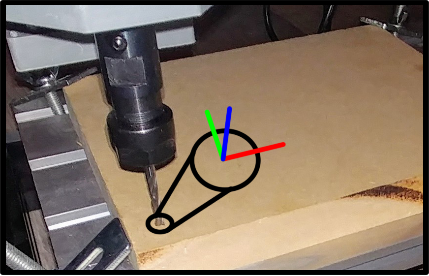
In doing so, and zeroing the X, Y and Z axes, you are telling the CNC that you want to ‘Start from here’. The router has to know where you want it to start before you start it, otherwise it will just assume things and almost certainly get it wrong. Part of getting the start position right is being aware of the size of the job you are going to start and where the .nc file expects to start from. The visualisation in candle and similar software when you load the .nc file can be very useful to work this out.
Positioning X and Y is easy enough, you want the center of your bit/end mill to be over the “origin,” the bottom left corner in the example above,and zero those out by hitting the key in Candle. You will see 2 out of 3 of the work coordinates turn to become 0. Now you need to zero-out the Z axis in order to have your work coordinates completely set. There are two ways to do this:
- If you have the 3018 Pro, or another CNC that does not have a Z-Probe, then you will need a piece of scrap paper, the thinner the better but not crumpled (this is important). Bring the end mill close to, but not touching the material and set your steps in the Jog menu to “.1”. Taking a small torn off bit of paper, place it between the endmill and the stock material and use one hand to continually move the paper back and forth, while using the other hand to lower the Z axis until you feel the paper snagging against the end mill. At this point you can say it’s good enough, or further dial in the settings by bringing steps to “.01” and continuing to raise/lower the bit until satisfied. Once it is in position, select the button
 to zero out the Z axis.
 - If you have the PROver or have modified your 3018 Pro to allow for a Z-probe, simply set up the Z probe (download video instructions & code here), and place it between end mill and stock material, and press the button
 .
.
Pressing The Button
With the correct bit installed, it doesn’t hurt to raise your end mill up on the Z axis (After Zeroing) just in case it drags when the file starts, which is a possibility with some CAM software.
Open your file and look at the visualisation in Candle carefully, especially the dimensions and where the origin is, make sure this matches the size, position and alignment of your stock. If everything looks good, take any & all safety precautions and Click Send.
Glossary of Terms
These terms and phrases are very useful in helping you (and anyone trying to help you) with tech support & troubleshooting.
Units
As in a unit of measurement, basically these will be in inches or mm, there are other variations for speeds such as mm/sec and mm/min . The software you will use to create things will have its own settings. It is imperative that the units match, if you tell your software to work in Inches and the router works in mm you are going to get very compressed results and vice versa, move left 1 is very different in mm and inches!
Controller or Motherboard
This is the bit of electronics which controls the movement of the CNC as well as the rotational speed of the spindle, or laser power. On a SainSmart CNC, an Arduino microprocessor system is utilized. The motherboard also has all the electronics needed to drive the stepper motors which control the axis movement, to drive the spindle motor at differing speeds and the laser at different power settings, translate GCode commands received via USB or an offline controller into pre-programmed movements, all while receiving and processing other commands, such as jogging the spindle around, changing settings, displaying it's status, etc.
Grbl
This is the software which runs on the motherboard; it basically takes GCode CAM software generates and translates it into the movements and speeds needed to cut out a desired shape. Grbl is free to use open source software.
Stepper Motor
A motor that is told to turn in small steps like turn clockwise 1.8˚ as opposed to a ‘normal’ motor that will try and continue to rotate as long as power is supplied. All of these routers use stepper motors to control the movement of the x, Y & Z axes; each step of the motor will turn the threaded rod a bit, which will move the things connected to it by a small amount. The amount the axes move depends on the stepper motor, the pitch of the threaded rod, the motor controller and the router motherboard.
Bed
This is the flat , rectangular aluminium surface which you place your stock material on top of. It also has slots in it for clamps to be attached.
Microsteps
Where the stepper motor is told to turn by a fraction of its rated step by application of fractional electromagnetic forces. This depends on the motor and the motor driver chip used on the motherboard, one microstep determines the minimum movement or precision of the axes, this also depends on the pitch of the threaded screws.
Missed Steps
You may often see this as a possible cause of errors, quite simply it’s when the stepper motor is told to move, but for whatever reason doesn’t. The causes can be varied, such as asking it to move too fast, or because the bit is cutting too deep in one pass and has now been told to move sideways putting too large a load on the stepper motor. The motherboard is calculating the position of the spindle based on what it has told the stepper motors to do, it doesn’t know if they have actually done them. If a step is missed, the position is now in error, causing the router to become misaligned.
PWM (Or TTL)
Pulse Width Modulation, which is often implemented by Transistor to Transistor Logic (TTL). You may see either on any control board connector, but practically they are the same. Simply put it is turning something on and off very rapidly (up to 1,000 times per second). Imagine you didn’t have a dimmer switch on a light but wanted it to operate at ½ brightness. Simple, stand by the switch and repeatedly turn it on and off where it is on for 50% of the time and off for 50% of the time. OK not recommended, it will probably give you a headache, but if you use a computer or electronics to do this 1,000 times a second all you will see is the light burning at 50% brightness. Change it so it is on 75% of the time and it will be brighter, less and it will be dimmer.
Spindle Motor
This is the ‘big’ ‘normal’ electric motor which holds the cutting end mill. The power it is supplied can be altered in order to chance the speed of rotation, which needs to be adjusted depending on the amount of work it is being asked to do.
Consider. Driving a car at a steady speed on a flat road, and then starting to go up a hill the car will start to slow down as the engine is having to do more work. In the same way, the motherboard uses PWM to vary the speed but provides no feedback to measure the speed. So it’s more of a power setting. Normally it is set as a maximum speed of 1000 even though the RPM of the standard Spindle motor will be higher, the best approximation of a true speed is about 8,500RPM under no load at the 24V supplied by the router motherboard. This value is not going to be linear, in other words a speed of 500 will not be exactly half the RPM of a speed of 1000.
Stock
The base material you are trying to engrave, cut or carve into.
ER11 Tool holder
The most common tool holder on this type of machine, it requires a couple of spanners to release and fasten by tightening or releasing the collet which clamps the tool.
Collet
The piece inside the tool holder which as it is tightened into a tapered hole contracts around the bit, clamping it snugly into place. This only tightens so far, of course, a collet has a limited range of movement around the bit, but the diameter of the hole in the centre determines the range of bit sizes it can clamp. The standard collet supplied with your CNC can take a bit with a shank of around 3.175mm (or 1/8”), but other collets are available, such as the SainSmart collet set which allows you to use bits with a shank diameter ranging between 1 to 7mm.
Tabs
If you, for example, are cutting out a shape all the way through to the spoilboard, then when you get towards the end of the cut there is nothing holding it to the bed other than gravity. In the worst case, your finished part will start to move as the last bit of material is removed, potentially damaging or destroying what you worked to create.
Tabs are where you set within the model a number of small nubs of material which should NOT be cut out to hold a centre piece in position, It’s like a coarse perforation round the edges of stamps! These have to be removed manually when the cut is finished.
Tiling
A technique for making things larger than your CNC can usually make.
Bit or End Mill
The sharp, pointy thing which rotates and cuts into the stock material. There are so, so many of these in every shape and size imaginable. Some are general use, some are for very specific situations.
Toolpath
Simply put, this term describes the path that the tool is tracing in order to do the programmed job. This is normally expressed by the software analysing the model, using the information you have told it about the tool, how fast to move it etc...... and generating a GCode file which tells the router what to do in small bites of code at a time; Move up a bit, down a bit, left a bit....... Often your software will provide a toolpath simulation so you can see on your computer what is going to happen before you send it to the router.
Limit Switches or End Stops
Switches which trigger at the limits of movement for each axis. Used to allow the router to establish a ‘Home’ position by moving around until they are triggered. In operation they will stop the router from trying to move past its physical limits by generating an alarm. Not fitted to the 3018-PRO, but comes standard with the PROVer CNC.
Soft Limits
This can only be used when a home position can be set via a homing cycle. It allows you to use 3 limit switches to detect the left, front and top limits, all that is needed to set a home position, rather than fitting 6 to also determine right, back and down limits. Soft limits set the maximum travel from the home position, the router software checks if a movement will exceed the machine limits and raise an alarm if it will, just as it would if a limit switch was activated.
Spoilboard/ Baseboard / Wasteboard
A bit of sacrificial material mounted on top of the bed and underneath the stock which can be levelled exactly. Baseboard, Wasteboard and Spoilboard are all the same thing. As for why you might use one, there are a number of reasons.
If you are trying to cut completely through the stock you are going to start cutting the aluminium bed. If, for example you are using a router bit to cut through wood it is suddenly going to make contact with a piece of aluminium which is a lot harder and it probably will get damaged, or possibly break, let alone the permanent damage it would do to the bed.
It is important that the bit (or laser movement) is absolutely parallel to the surface of the stock. Imagine if the right hand side was 1mm lower than the left. If engraving for example this would probably mean that if you started on the left by the time you got to the right the bit may not even be touching the surface. If routing or carving your cuts may be too deep or shallow.
Using a Spoilboard mounted permanently and securely means you can use a bit to slightly level or face the surface which makes the top level with the movement of the bit. Even if the level of the bed is slightly tilted, after facing it the top of the Spoilboard will not be, as long as it is securely mounted and is not moved.
As an extra step, you can engrave your Spoilboard with a grid. These lines are exactly parallel with the actual movement of the bit or laser which makes aligning the stock to the actual movement, even if the bed itself is a little skewed, making it much easier.
Coordinate systems
When you turn on your router it has no idea where it is on any of the axes, it doesn’t save it's position and even if it did you could have manually changed them. You need to know these things for the CNC, as well as how they relate to each other to stop your machine from potentially damaging itself in the worst case,, suddenly deciding to plunge down as far as it can or banging against the physical limits of the machine.
Home/Machine Coordinates
The Home position is where the spindle is when you turn it on! That is, unless you have limit switches. This allows the use of a homing cycle where it moves to test when the switches activate so telling it where a ‘Home’ position is. This is normally the spindle being at the bottom left corner and as high up as it can go. This position cannot be set via commands to the router other than telling it to perform a homing cycle.
Safe Position
Often software will generate GCode using the G28 series of commands which specifies a ‘safe’ position to which it should return to. This is RELATIVE to the home position and it is remembered by the router. By default, unless the router receives a G28.1 command, which will set a new safe position, it will be an offset of 0 on all axes from the Home position, so if you don’t have a consistent ‘home’ position it can rapidly become an ‘unsafe’ position.
It is with noting that Fusion 360 generates the GCode with moves to the ‘safe’ position on by default, but you can turn it off in the Grbl post processor options, turn G28 Safe retracts off. Imagine the following circumstances: When you turn the machine on the end of the bit is 1mm above the top of the Spoilboard. Jog the bit out of the way. You mount some stock, lets say 5mm thick using clamps on the Spoilboard. You run a milling job. At the start the code tries to send the bit to the home or safe retract position, normally first moving to the Z axis safe position then to the XY axes safe position in a straight line. At the end of the job the bit is returned to the home position the same way.
The clamps and what remains of the stock are probably in the way, this can be disastrous as it tries to smash its way through things. Sometimes you will see people reporting that at the end, sometimes the start, of a job that the bit is dragged across or through the surface marring the stock or starts by plunging straight down. This is the probable reason why.
Work Coordinate System (WCS)
Sometimes referred to as Local Coordinates. This is what you will probably be using for every job! This is basically a set position for the start of the work, or work origin. Even if your machine knows its home position it’s still going to base an operation on WCS as it’s easier to position the bit or laser relative to the work origin. In other words jog the bit or laser to where you want to start the work, tell the router this is the WCS zero position and go from there.
It is your responsibility to make sure that you are not going to tell it to go outside its physical limits. It is also your responsibility to make sure that the router can get to the start position without damaging anything, for example don’t leave the bit below or exactly on the surface of the stock! The first command sent to the router may well be to go to the WCS Origin or wherever the toolpath starts. This will be in a straight line so if there is something in the way?
Your Software will normally allow you to set a home position on your work before generating the GCode, Fusion360 is an example of this, you can set the origin of the work coordinates to bottom left, top right or anywhere else you chose normally relative to the stock. Top Bottom Left seems to be the most common but beware! If they don’t match the physical environment, stock position, starting position etc. of your router then there will be problems ahead.
Jogging to the start position is NOT enough depending on the software you are using, you must also register this as the starting position. Or your router may first go to where it thinks the start position is before starting. Within the Work Coordinate System (WCS) there will be a few buttons you can press on your PC. One will be to set the current position as the origin, In Candle this is the Zero XY and Zero Z buttons, in LaserGRBL this is the globe along the bottom of the screen.
Absolute vs Relative Coordinates
The router will use either relative (G91) or absolute (G90) coordinates depending on the last one of these instructions it received. Relative means go 5mm to the right of where it is now, absolute means go 5mm right from the Home position or Work coordinate system origin Jogging.
Jogging
This is a term used for manual movement of the spindle using buttons on the computer or offline controller. These move the spindle around by varying, settable, amounts and are normally used to move to the Origin needed to start a job, or to move the bed to the front and the spindle out of the way to give easier access to set up a job.
NOTE: If using jogging to move to the origin of a WCS then putting it in place is not enough, you will also have to specifically tell the router that this is where you want to start from by zeroing all the axes.
Feed
The rate/speed which the end mill or laser is moved through or over the stock; this is controlled by the axial stepper motors. normally expressed as mm/min, and that is what the 3018-PRO uses by default for feed rates. There are many other ways of measuring the feed rate, some depend on the bit you are using to try and calculate how much each cutting edge is cutting out of the stock. This is normally best left to the professionals for the moment.
Speed
The speed of rotation of the spindle(Sxxx), for a laser the power it operates at. Remember that your GBRL based CNC has no measurement of the actual spindle speed or power, so mostly this works out to be faster and slower.
Passes
This is basically the number of times you tell the router to retrace the same path, probably with a lower Z axis value each pass. If you want to cut a groove or pocket in a piece of wood 5mm deep you are not going to do it in one single, go down 5mm then cut! If the wood is very soft and the bit is very sharp, maybe, but you take the risk of overloading the router, wearing out or breaking the bit by trying to make it do too much work in one go. You can get round this by telling your CAM software to make multiple passes cutting out a little each time. As a general rule the less material you take out the better the finish quality but the longer it takes. This also depends on the hardness of the material, you would need more passes using smaller cuts on oak than you would on a soft pine. Take notes so next time you have a better idea where to start!
Z-Probe
A Z-Probe is a simple device, it’s a piece of conductive material with a wire attached (Or a spring loaded switch). Another wire is connected to the router and clipped to the bit in the spindle motor. (it’s a switch) Very simplistically the bit is lowered onto the stock until contact is made. This tells the router where the origin of the Z axis should be.
Offline Controller
This is a small module with an SD card which connects directly to the router Motherboard. It can read a GCode file from the SD card and send it to the router. A bit limited in what it can do but very useful if your PC is too far away from the router or you don’t want to tie it up for the duration of a longer job. NOTE: You cannot connect the offline controller and a USB to the router at the same time! They use the same serial interface on the router and it will get very confused! Also the offline controller has a USB interface which allows it’s SD card to be used by the PC as a drive. Don’t use this while the Offline Controller is talking to the router!
Vref
The router motherboard contains motor drivers for each of the stepper motors. Depending on the stepper motors you have the maximum amount of current each driver can supply is controlled by a Voltage reference or Vref which is set by turning a small trimmer pot on each motor driver. This can be adjusted by turning the trimmer pot using a very small screwdriver and measuring the voltage from the pot to ground. The exact setting depends on the stepper motor and the motor driver chip. Too high and the driver will try and provide too much current and probably burn out. Too low and the stepper motor won’t get enough current and could miss steps.
CAM (Computer Aided Manufacturing) Process
Basically this takes a model, be it a picture, 2D or 3D model and determines how the tool needs to be moved in order to create the GCode necessary for the router to carve or engrave the part out of the stock material. This is called generating the toolpath which is then converted to GCode.
In order to do this it needs to be told things like what tool it is using. This can make a big difference if you are using someone else’s GCode file! If they built the GCode to use a 20˚ engraving bit and you are using a 3mm routing bit or vice versa the results are not going to be good! Also you are not going to be able to carve or drill a 2.5mm hole using a 3mm bit. And if you are trying to carve aluminium rather than soft pine you will certainly need to tell the router to use a slower feed rate to move the bit and a different spindle speed.
CAD (Computer Aided Design) Process
This is defining what you want without having to, at this stage to specify how to make it. This could be a 2D graphics processor (engraving Jpegs) up to a full 3D modelling system. The output of this is fed into the CAM process. Unfortunately this does not mean you can totally ignore the manufacturing process even when designing things, you are not going to be able to make a 90 degree internal corner when using round router bits, you will have to add a fillet (radius on a corner) size suitable for the router bits you have and intend to use.