If you want to get into PCB milling, height mapping is absolutely essential to producing functional board prototypes. What this process does is sample the surface height at regular intervals within your project's work area, forming a grid which the CNC can later reference during the engraving process to make sure that the surface of your PCB is engraved at an even depth.
This guide will walk you through the process of using this feature in your next project:
Part 1: Setting up your Project for Height Mapping
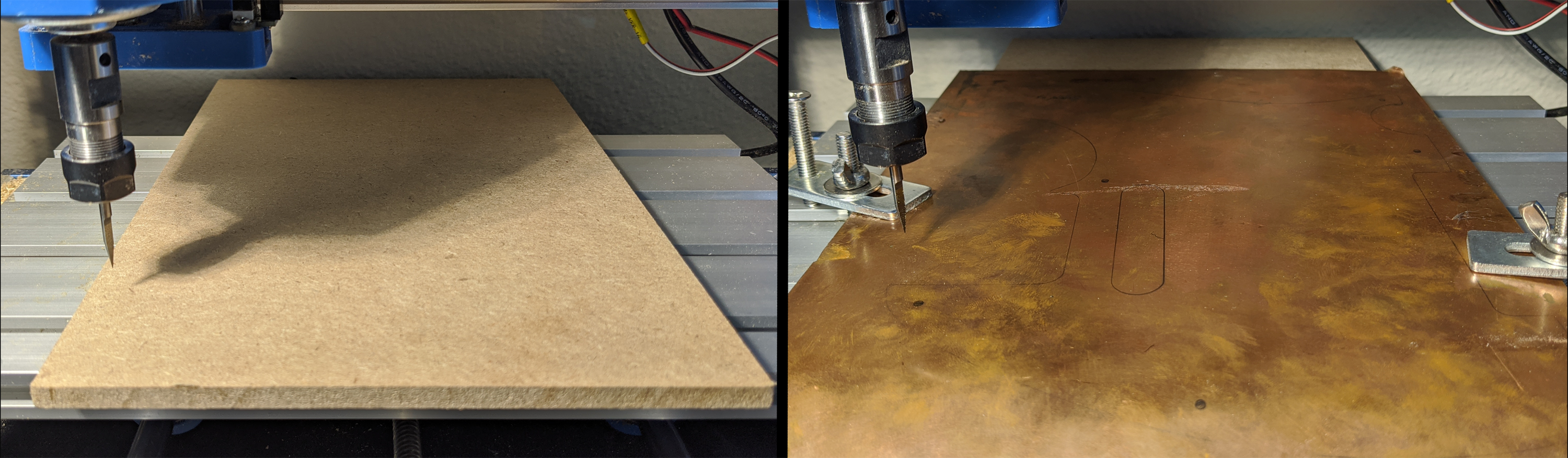
Most stock materials you would need to height map like PCB's are quite thin to begin with, so to make sure the engraving bit has room to reach it, you may want to consider placing some sort of spoil-board underneath as shown here:
At this point, you will now need to follow the setup procedures for candle, which can be found here. This included opening your project, jogging your CNC into position on the X & Y & Z axis and zeroing out everything. See this guide if you want to zero Z with your Z Probe.
If you have a PROVer CNC then it comes with a Z probe standard, but alternatively, if you have a 3018 Pro CNC, you will need to buy the probe as an accessory. For the latter, the the wires must be soldered or otherwise secured to the A5 Pins on your board; the Red, positive lead, connects to the upper pin of A5 and the Black, ground lead, connects to the lower pin of A5.
With X and Y zeroed, and Z Probed, the last step you will need to do is manually jog your Z axis downwards until the tip of your engraving bit or end-mill is less than 1 mm from the surface of your stock material. DO NOT RE-Zero Z at this point.
Part 2: Modifying your Z Probe
Now that you have used your probe as is needed conventionally, next we will have to make some non-permanent modifications in order to use it for Height Mapping.
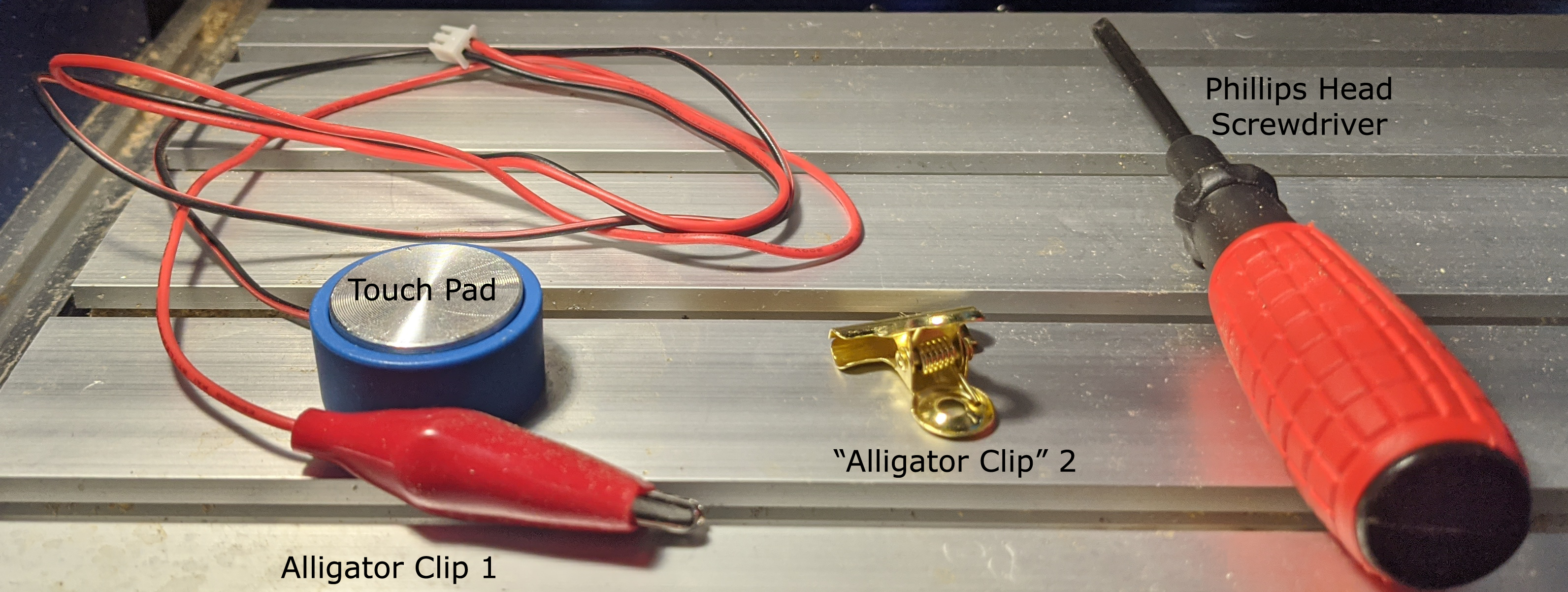
Usually how a Z probe is meant to be used is that you connect the red lead with an alligator clip on to the side of your engraving bit or end mill, and place the round touch pad underneath. The idea is that when the end mill comes in contact with the touch pad a circuit is completed and the CNC knows where the surface of your material and stops itself from moving any further down.
Here's what you'll need for this step:
To be used for height mapping, you will need to make some non-permanent modifications in order to replace your touch pad with "Alligator Clip" 2:
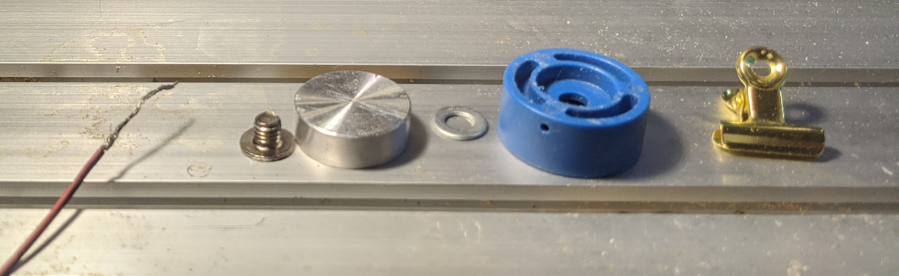
Turn the Touch Pad upside down and use your Phillips head screwdriver to fully remove the screw which holds everything together. Fully disassemble the entire touch pad, taking care to keep the parts organized and somewhere they won't be lost; be extra careful pulling the wire out of the blue plastic base, as it would be bad if you tear it by accident. Afterwards it should look something like this:
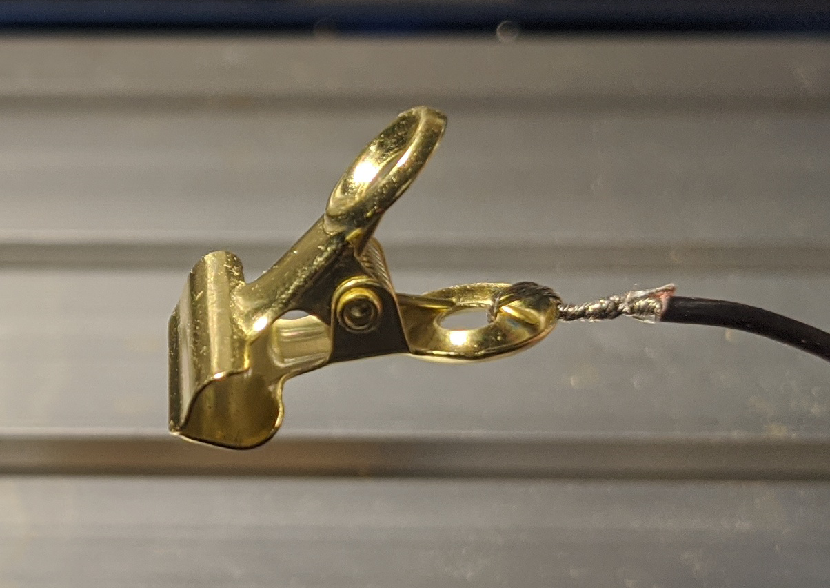
gently twist the copper wire strands that are exposed so that you can bend it like one piece and then fasten it to your "Alligator Clip" 2. In the case of the above, this copper clip was something that was left over from a previous project; if you're going to use substitutions like this then make sure to know what material it is made of. Non-conductive metals like aluminum would not work, for example. The twisted copper wiring was fed into the lower eyelet on the clip and then folded back onto itself, twisting further to secure. However you fasten your second alligator clip, take care to make sure it is secure enough to carry an electrical current. The finished product:
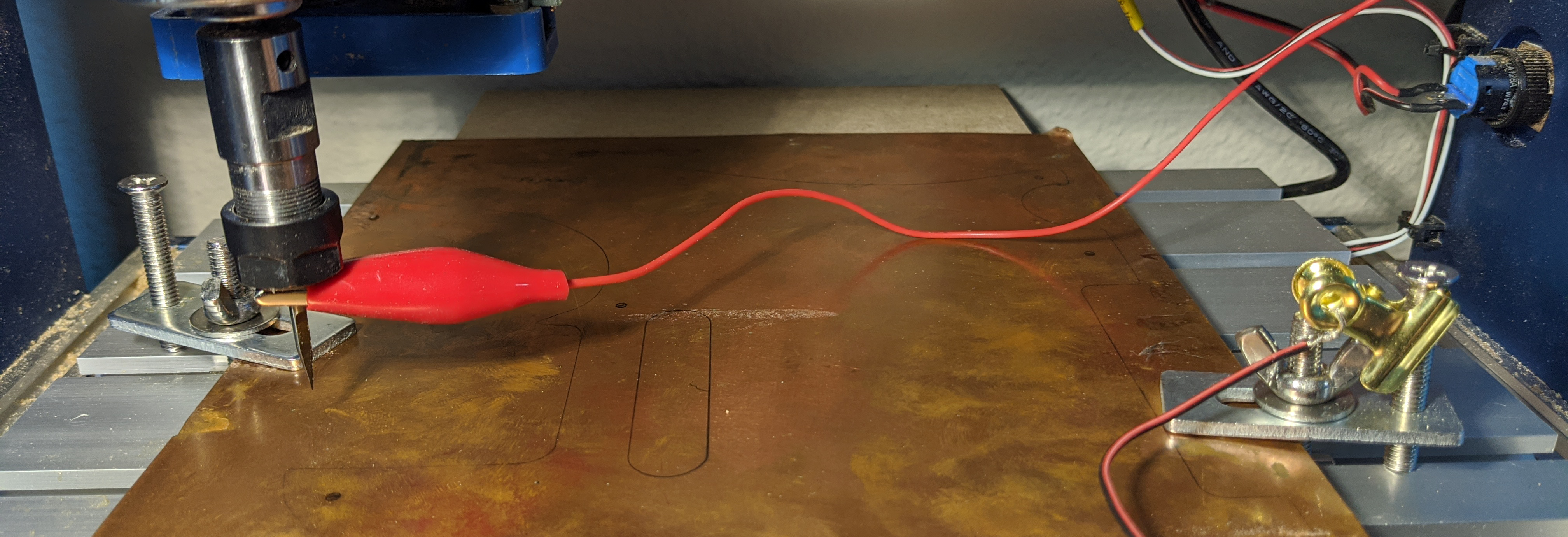
Attach Alligator Clip 1 to your End Mill/Engraving Bit, and Alligator Clip 2 to either your work material itself, or your clamp as was done in the image below:It is important to make sure, before continuing that your prove will form a complete circuit every time the tip of your end mill touches your project. This is ensured in the case above because everything, the engraving bit, the clamps and the stock material are all electrically conductive. Your stock material must be conductive at least on its surface for a height map to be created.
Part 3: Configure & Run Height Mapping in Candle
Assuming you have been following along step by step, you will next need to find the Height mapping tap and expand it to show all of the options, it is minimized by default. From there, follow these steps:
Select the Checkbox next to "Use Height Map" so that it is enabled
Select the Create button under where it says "Map:"
Within the height map settings, there is a button called Auto, which automatically resizes the height map workspace based on your project.
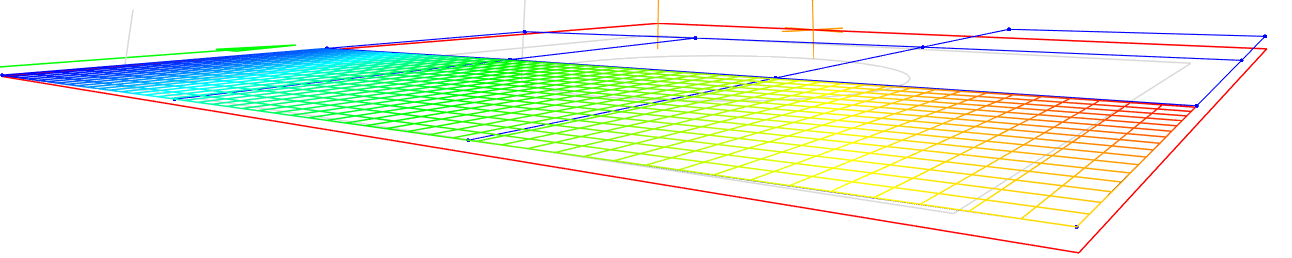
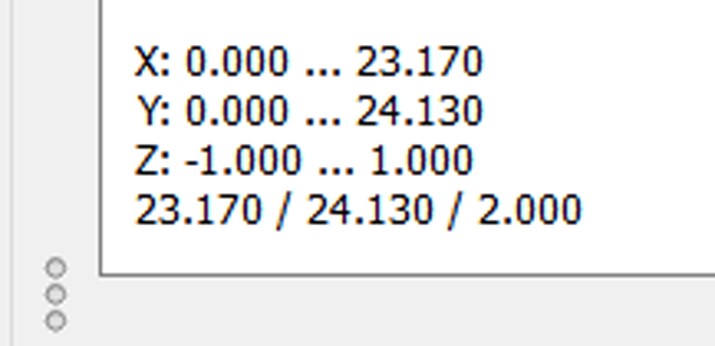
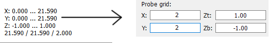
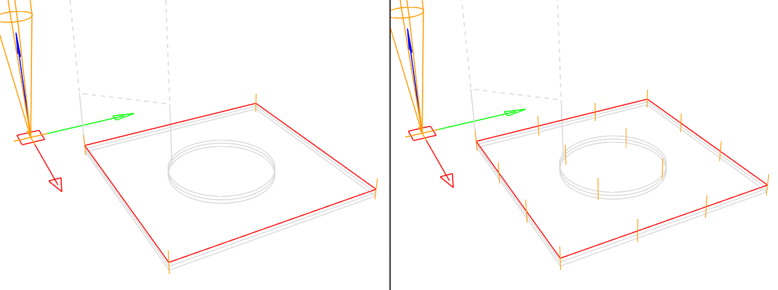
Look at the bottom right corner of the preview window to find this information:This tells you how tall and how wide your project work space is (These values change after auto button is selected) and you need that information in order to alter some settings. For X and Y separately, divide the value by 10 and round to the nearest whole number. In this case X = 2 & Y =2. We do this because the best trade off between time and quality is spacing each probe sample 10 mm apart. You can do more or less as suits you. Enter the final Values in the Probe Grid section of Height Map Settings:Here is a comparison of a 2 x 2 sample map versus a 4 x 4:As you can see, in the first image only the 4 corners are sampled, versus the second where there are 16 locations sampled.
You are now ready to generate your Height Map. In the center of Candle, at the bottom, you will see that you can select Open, Reset or Probe. Press Probe now. This will begin the height mapping, your CNC will move during this process but the spindle will not turn on.
Once the map is complete you will see some rainbow colors show up in a grid on your project such as the one at the one at the beginning of this article. Select Edit in order to exit the Height Map creation process. The rainbow illustration will disappear once you have done so, but do not worry, the data is still there.
It may seem counter-intuitive, but should you want to save your height map for later use, click Open in order to be prompted to save your map.
Disconnect Alligator Clip's 1 & 2 and store them safely out of harms way.
Select Send at the bottom-center of Candle to start your engraving. Your CNC will now refer to the Height Map for this project, giving you an even engraving.