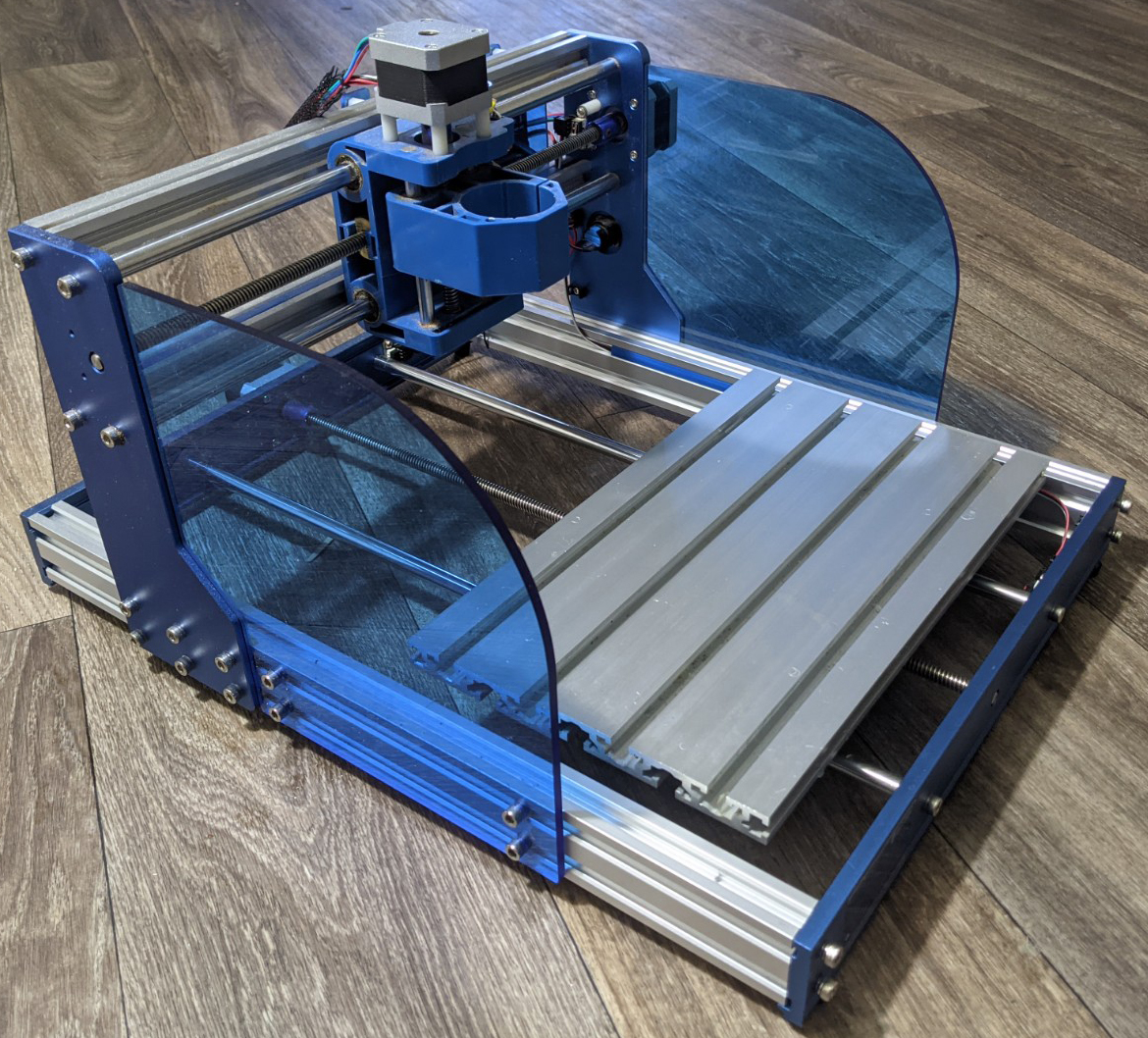
Genmitsu CNC Y-Axis Expansion Guide for 3018 Series CNC Router

Things you will need:
Step 1: Disassembly
Disconnect & Remove All Wires Connecting to the Base of Your CNC
Before you start taking your CNC apart in earnest, it is best to start by disconnecting all wires related to the Y axis, including wiring for limit switches (If using a PROVer CNC) and even going as far as to cut any zip-ties securing the wires. Replacements for the latter were included with your expansion kit for replacing these.
Unscrew the Gantry Assembly from Either Side of the CNC's Base
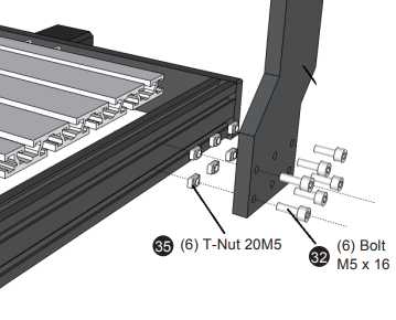
On each side of your CNC there are 6 M5*16 bolts which attach it through the frame, before you go any further you will want to remove all 12 bolts and then remove the entire gantry assembly, placing it to the side.
If you have a PROVer CNC, also take this chance to remove your two acrylic side plates.
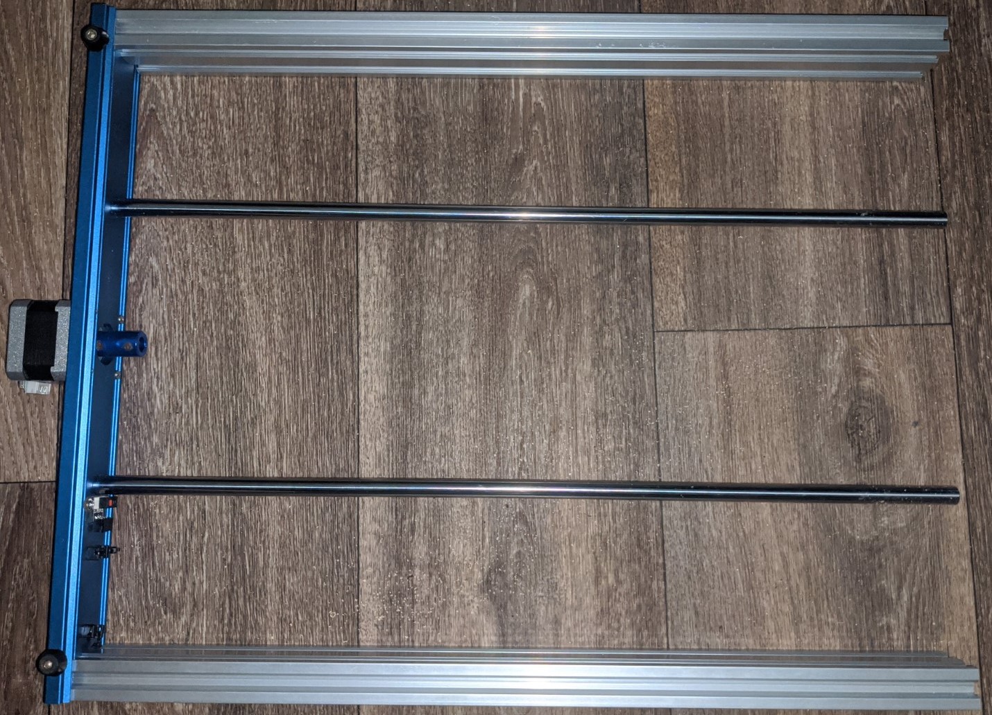
Take Apart Your Frame
Before you start: Do not remove the stepper motor from the rear plate, this is not needed for the upgrade. Likewise there is no need to disassemble the bed itself. Instead, simply loosen the set screws that join the lead screw and stepper motor and this can slide out after disassembly.
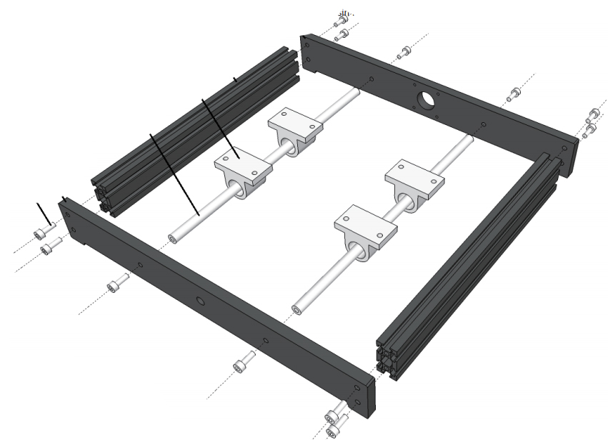
There are a total of 8 M5*16 bolts which hold the rear and front panels to the side extrusions, as well as 4 more which hold the linear rails in place, all of which need to be removed and put aside for later use. While doing so, also take a moment to slide the 12 T-Slot nuts out of the side extrusions and place them next to the other bolts for use during assembly.
At this point, take the 2 side extrusions as well as the linear rails and place them to the side, as these will be replaced.
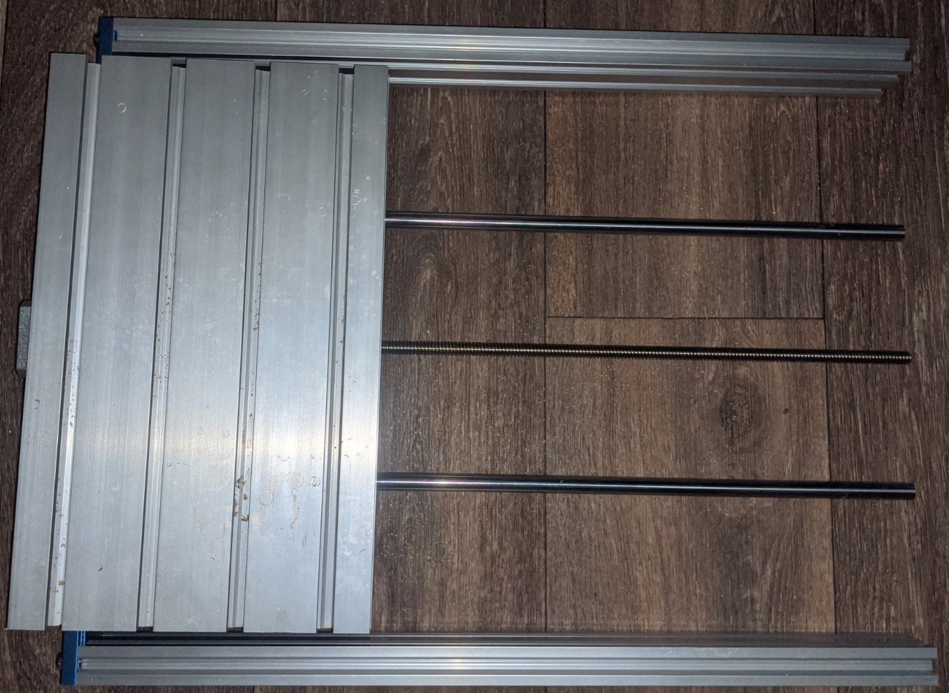
Step 2: Gather All of Your Components
Before moving forward with the final assembly, it is best to take a moment and organize all of the parts you have accumulated, as shown in the image below:
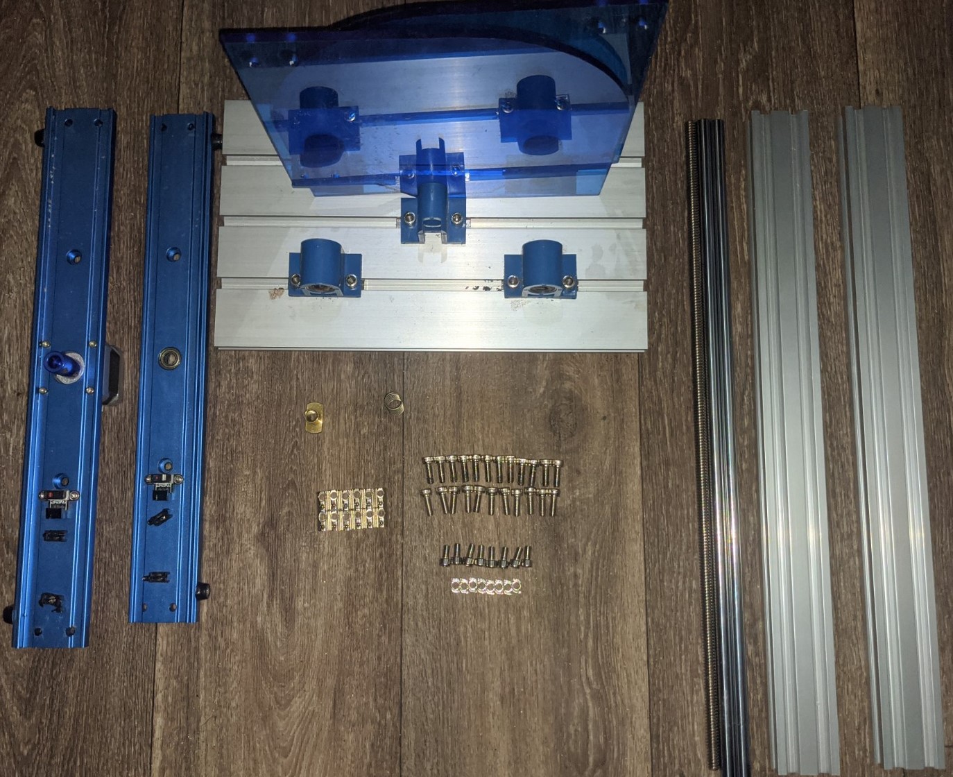
Parts List:
- 1x Assembled Front Panel
- 6x M5*16 Bolts for Front Panel
- 1x Assembled Back Panel
- 6x M5*16 Bolts for Back Panel
- 1x Assembled CNC Bed
- 1x Spring for CNC Bed
- 1x Copper Nut for CNC Bed
- 2x Acrylic Side Panels
- 8x M5*10 Bolts For Side Panels
- 8x T Nut M5*20 For Side Panels
- 2x Extended Side Extrusions
- 12x Slider nut M5*20
- 2x Extended Linear Rails
- 1x Extended Y-Axis Lead Screw
Parts to be Discarded:
- 2x Original Side Extrusions
- 2x Original Linear Rails
- 1x Original Y-Axis Lead Screw
Step 3: CNC Base Assembly
Attach the Extended Side Extrusions & Linear Rails to the Back Panel
Install Extended Lead Screw into CNC Bed Through Spring & Copper Nut
The CNC bed is assembled as follows, with the spring and copper nut:
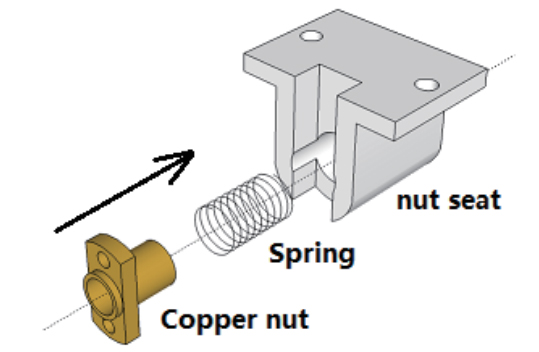
For assembly, you will need to hold the copper nut and spring in a compressed condition in the notched opening of the Nut Seat while continuing to screw in the Lead Screw through the rear of the nut seat until the copper nut is engaged on the threads. Continue screwing the Lead Screw until it is approximately centered on the Nut Seat.
Install the Bed with Threaded Lead Screw Into the Liner Rails Already Attached to Back Panel
Secure the Lead Screw to the Y-Axis Stepper Motor through the Coupler
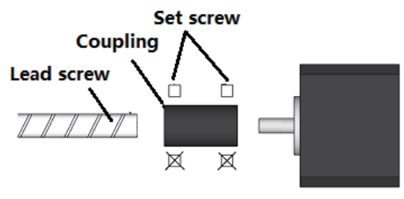
Don't forget to tighten the set screws on the coupler in order to lock things down.
Install the Front Panel & Square Frame
The front panel installation is easy enough, but squaring the frame requires some additional explanation.
A properly squared frame will keep your CNC Y-axis from binding up or meeting resistance, and in order to do this, you will need to slightly loosen all the M5*16 bolts on one side, slide your CNC bed all the way to that side, and then tighten all the bolts back up again. Repeat the same process on the opposite side.
At this point your CNC frame should be fully assembled and ready to be paired back up again with the Gantry assembly.
Step 4: Final Assembly
The process of mating the base frame with the gantry assembly mirrors the same process as when you assembled your CNC for the first time, the only major difference is that rather than having the gantry spaced 46.5mm from the rear of the frame, you are now going to want it to move more forward in order to take advantage of the expanded Y-Axis.
Rather than give you a specific number, it is strongly suggested that you move the gantry as far forward as your wiring will allow. This is usually around 60-80mm depending on whether you have limit switches.
Cable Routing
The stock wiring does allow for the use of stock wiring without issue, just take your time and keep the wiring clear of any moving parts. In order to help you with this, here are some things to keep in mind:
Labeling
Each cable is labeled at one end with its purpose and this corresponds to the markings of where it fits into the motherboard. The label end goes into the motherboard.
Cable routing
Most of the cables are static; they will not move as the router working, these must be routed so that in operation they are out of the way of the bed including anything which may be mounted on it and the spindle. There are three sets of cables which will move as the router operates; these are the Spindle motor cable, The Z-axis limit switches and the Z-axis stepper motor Cable. These must be left free to move to allow the X and Z axis a full range of travel.
Cable Protection
A length of Nylon cable protector was provided with your CNC which slips over one or more cables and can be held in place with a cable tie at each end. It is strongly recommended that this be used on the free moving cables to protect them from any abrasion damage. Hint: Tape the plug or plugs to the end of something like a pencil using masking or other tape. Then slide the pencil through the inside of the tube pulling the cable(s) with it, the tape also helps prevent the corners from catching on the inside of the tubing.
Securing to the Cable Holders
Run the cable(s) along the center of the holder then place a tie wrap through the end holes and over the cable(s), wrap it over the top and tighten it. Trim off the end of the tie wrap.