MX3 Controller Specifications

Controller Features
- Compatible with Mach3 or DrufelCNC software running on any of the following operating systems:
- Windows XP
- Windows 7 (32/64)
- Windows 8
- Windows 10
- Communicates through USB or Serial Interface
- Supports Z-Axis automatic probing
- Emergency Stop Feature
- Limit Switches
- Onboard Stepper Drivers (32 micro step max)
- Maximum output pulse frequency 100KHz
- Electrical interference protection
- Supports External MPG hand wheel for manual control
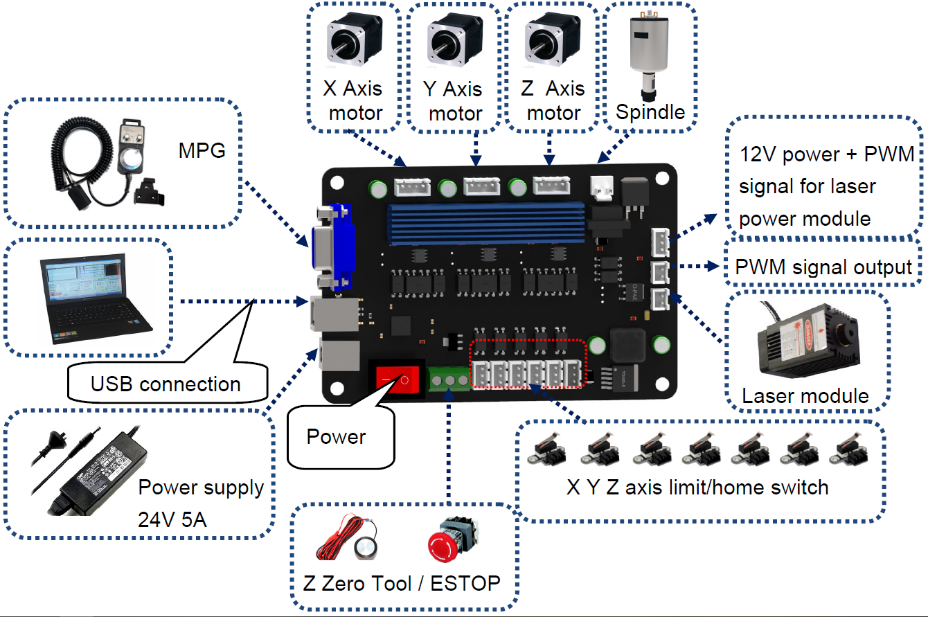
Basic Connection Diagram
PCB Label Description
Abbreviated Label on Board | Description |
MPG | MPG interface |
USB | USB interface |
24VDC | 24V power interface |
ON | Power ON |
OFF | Power OFF |
COM | Input signal common |
ESTOP | Emergency stop switch interface |
PROBE | Z Zero Tool interface |
XLIM+ | X limit switch + |
XLIM- | X limit switch - |
YLIM+ | Y limit switch + |
YLIM- | Y limit switch - |
ZLIM+ | Z limit switch + |
ZLIM- | Z limit switch - |
LAS | Laser module interface |
PWM | PWM signal output interface |
12V | 12V power output interface |
GND | V-(0V) |
Spindle | Spindle motor interface |
X | X Axis motor interface |
Y | Y Axis motor interface |
Z | Z Axis motor interface |
USB.PWR | USB power indicator LED |
24V.PWR | 24V power indicator LED |
SPINDLE | Spindle working indicator LED |
LASER | Laser working indicator LED |
ALM | Stepper motor driver circuit alarm indicator LED |
RUN | Stepper motor driver circuit working indicator LED |
MPG Interface pin definition
Support for external connect electronic hand wheel, use HDR15 interface to connect electronic hand wheel, Interface pin definition as shown below, You can purchase a hand wheel connector according to the specifications, or you can purchase one of the two that we sell.
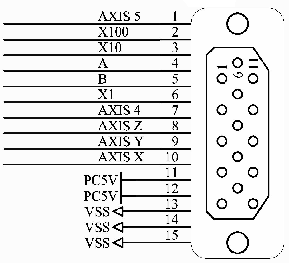
Note: The hand wheel does not directly control the motor operation, but controls the motor through software. When the electronic hand wheel is rotated, the software coordinates will change.
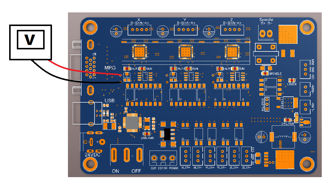
Driver Current Regulation Method
Should you need to alter the factory standard settings:
Taking the X-axis as an example, turn on the power supply, measure the reference voltage of the X-axis drive with a voltmeter, and select the potentiometer with a screwdriver to increase or decrease the reference voltage. The larger the reference voltage, the larger the drive current. Drive current calculation formula: I=8.3*V/1.1, for example: reference voltage is 0.2V, drive current = 8.3*0.2/1.1=1.5A
This can be repeated for every axis.