How to Install Limit Switches in your Genmitsu 3018 Pro with Only Your CNC

Based off of the works of Corey V.
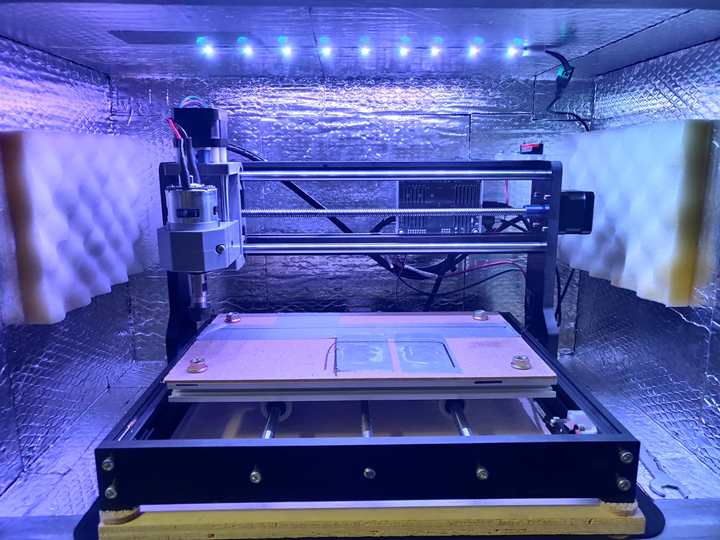
This project file and tutorial are designed for the SainSmart 3018 Pro. This tutorial guides you through the process of adding X, Y, and Z-axis end stops/limit switches. This allows you to protect your machine from violent crashes, damage, and other unfortunate incidents. It also allows you to “home” the machine so you can get repeatable and consistent machine coordinates.
Materials Required
- 1 sheet of 6 mm (5.5 mm) cast acrylic which is at least 90 x 110 mm (SainSmart)
- 1 sheet of 12 mm (11 mm) cast acrylic which is at least 90 x 70 mm (SainSmart)
- 2 x Roller Limit Switches (V-156-1C25) (Amazon)
- 2 x Long Actuator Limit Switches (V-153-1C25) (Amazon)
- 2 x Snap Action Limit Switches (V-15-1C25) (can be made by removing the actuator of either of the two above or purchased at Amazon)
Hardware Required
- ~20 x M3 Cap Head Bolts of various lengths (Amazon)
- ~10 x M3 Counter Sunk Bolts of various lengths (Amazon)
- ~15 x M3 Nuts (Amazon)
- 2 x M5 washers (Amazon)
- 2 x M5 3030 t-track nuts
- 8 x M3 2020 t-track nuts (Amazon)
- 12 x 4.8 mm spade connectors (Amazon)
- 6 x paired female Dupont connectors (alternatively, 12 x single female Dupont connectors) (Amazon)
- Various length of paired cable (Amazon)
- Heat shrink (or electrical tape) (Amazon)
Tools Required
- 3.175 mm flat end mill (Amazon)
- 3.175 mm flat spiral end mill (SainSmart)
- 2.4 mm end mill (SainSmart)
- 3 mm (1/8") drill bit (Amazon)
- 2 mm (5/64") or 2.4 mm (3/32") drill bit (Amazon)
- 6 or 8 mm counter sinking drill bit (Amazon)
- Soldering Iron and Solder (SainSmart)
- Superglue / Masking tape (or other adequate work holding)
- Machinist Square (optional)
- Calipers (optional)
- Z-axis probe (optional)
Fusion 360 files included in this project
F360 Files:
- Download Link: 5.5 mm Stock File
- Download Link: 11 mm Stock File
5.5 mm thick acrylic sheet
This sheet contains the X-axis and Z-axis holders. It also contains a spacer for the right-side X-axis limit switch. This milling operation is two-sided so special attention must be paid to work holding and consistency between setups. Remember the double sided operation requires precise work holding for WCS. You can fashion a makeshift machinist square by gluing two small pieces of wood together to form a 90° angle. Alternatively, you can use the reference pin method.
There are also tool changes required between some of the operations, so it is recommended you run each operation separately to make sure you do not have issues. For this sheet you will need:
- 3 mm flat end mill for facing off the individual pieces (facing exposes the 2020 extrusion alignment rail)
- 3 mm drill bit for drilling the various M3 sized holes
- 3.175 flat spiral end mill for cutting out each part with tabs
- 2.4 mm end mill for pocketing holes for M3 nuts
11 mm thick acrylic sheet
This sheet contains the Z-axis trigger block and the Y-axis switch holders. These are thicker to meet the required tolerances for the related axes. You can either source 11 mm thick acrylic, or you can glue two of the 5.5 mm sheets together. Superglue works well to attach the two sheets. Be sure to remove the protective masking tape from the acrylic before gluing. Also, a light scuff with ~200 grit sandpaper before gluing helps adhesion between the layers without affecting finish.
There are also tool changes required between some of these operations, so it is recommended you run each operation separately to make sure you do not have issues. For this sheet you will need:
- 3 mm flat end mill for facing off the individual pieces (facing exposes the 2020 extrusion alignment rail)
- 3 mm drill bit for drilling the various M3 sized holes
- 3.175 flat spiral end mill for cutting out each part with tabs
- 2.4 mm end mill for pocketing holes for M3 nuts
For work holding on all of these pieces, it is recommended to use the superglue and masking tape method. Clamps will get in the way of some of the operations and you risk damaging your tools or the machine itself.
Note: verify the actual thickness of your acrylic sheets. If they are different, please update the Fusion 360 model and re-generate the toolpaths. Also, if you plan on using different tools for the above operations, make sure you update the tools (and associated feeds and speeds) and regenerate the tool paths.
Electrical & Wiring
After the milling operations are run, measure the lengths of wire you will need for each limit switch. Cut wire to length and solder the female spade connectors and female Dupont connectors to each end of each pair. Make sure to heat shrink the solder joints.
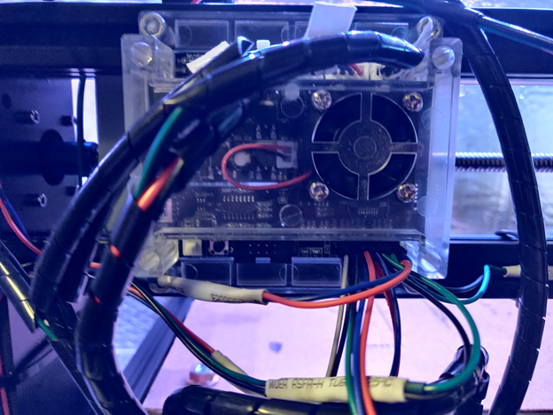
The spade connectors should be connected to the NO (normally open) and COM (common) terminals of the switches. The Dupont connectors should be connected to the associated header pins on the GRBL control board. The Woodpecker 3.4 board that comes with the SainSmart 3018 has dedicated header pins for each axis. Caveat: the X and Z axes are reversed. Apparently, the silkscreen was messed up during production. So be sure to connect your X-axis to the header pins marked with Z-axis, and vice versa.
X-axis and Y-axis
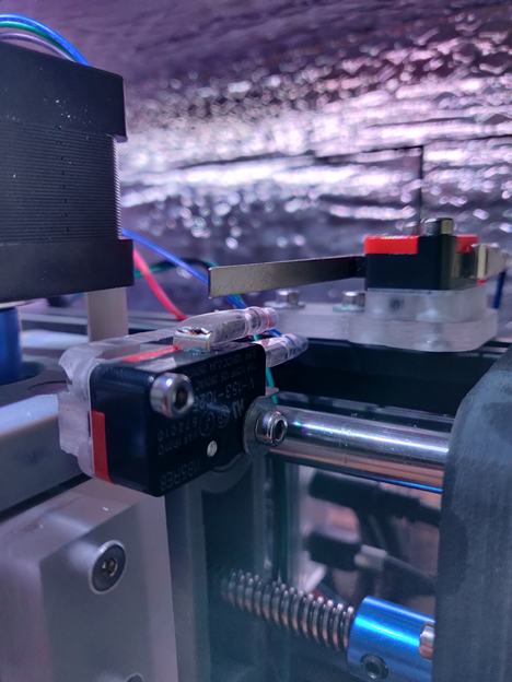
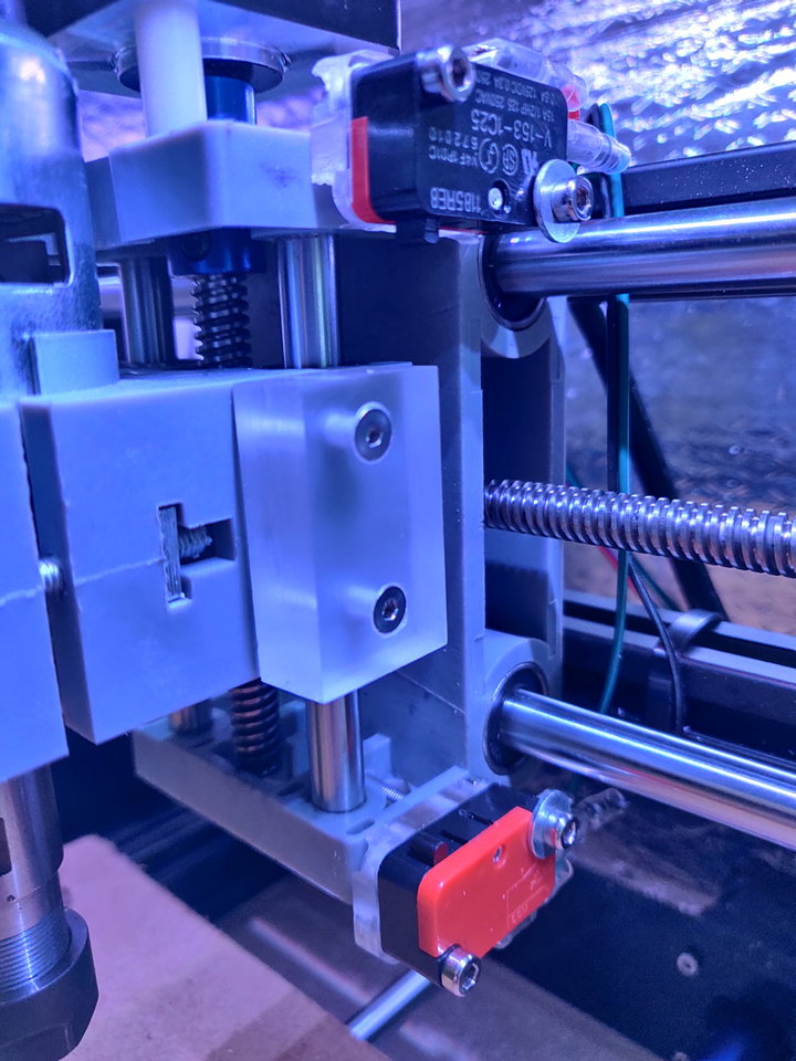
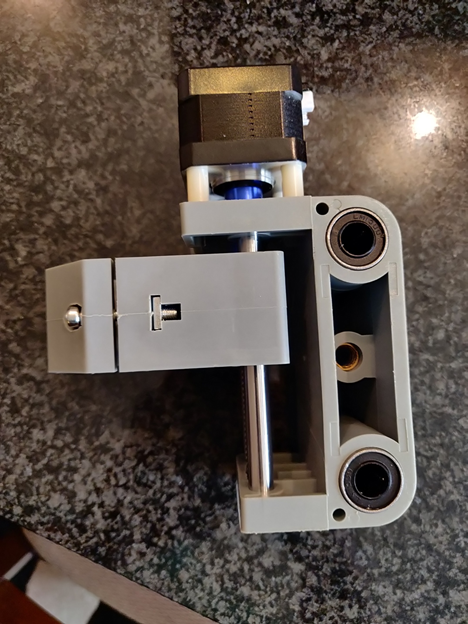
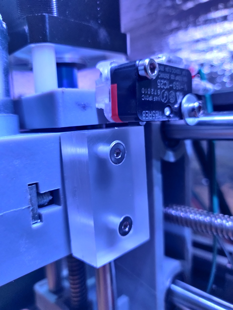
The X-axis uses the long reach limit switches and the Y-axis uses the roller style limit switches (as pictured). These switch holders have built in adjustment and tolerances that can adjusted manually until the switches actuate in the appropriate position. In other words, these holders are designed to be infinitely adjustable.
The right side X-axis will require an additional spacer/riser to clear the wires and the Z-axis switches (see photo below).
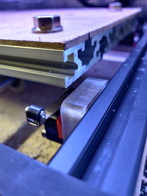
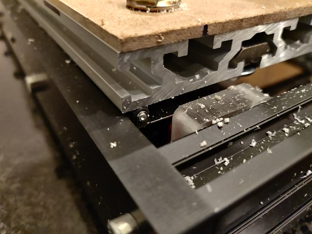
The Y-axis requires some M5 washers and 3030 t-track nuts at the end of the work platform. You will have to tune the location of the switches with the location of the washers. The washers will actuate the roller switches as the washer and work platform rolls over them (see photos below).
Z-axis
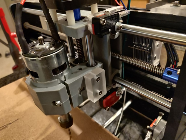
The Z-axis uses the basic snap action limit switches, which are designed to fall flush with each extreme top (+) and bottom (-) of the Z-axis. That is, when the Z-axis trigger block hits the switches, the Z-axis will be at its extreme. To accomplish this precision takes patience.
This axis is a bit more tricky than the other two. This axis requires you to drill into the Z-axis/spindle holder with a 2 mm (5/64") or 2.4 mm (3/32") drill bit. The locations of the holes must be precise as there are linear rails in the path of the drill hole. Preferably, use a center punch to mark the holes, and a drill press to drill the holes. You will be threading directly into the hard molded plastic.
The holes for the M3 bolts holding the switches for the top (+) and bottom (-) of the Z-axis are drilled at the midpoint of each end of the C shaped Z-axis (see photo below). The top and bottom ends of the C shaped Z-axis are 10 mm thick each, thus the midpoint is 5 mm. Align the switch holders with the trigger block (which is attached to the moving part of the spindle holder). However, pay special attention to the linear rails and other critical parts of the Z-axis.
Once your pieces are aligned, mark your holes, use a center punch to precisely locate the hole positions, and drill out the holes using a 2 mm (5/64") or 2.4 mm (3/32") drill bit. With a slightly smaller drill bit, you must make sure your holes are plumb and square to the work piece, so a drill press is recommended.
Some of the bolts will be able to accept a nut, but some others will be self-tapped into the hard cast plastic spindle holder. Screw each bolt carefully with firm positive pressure and they will be threaded into the plastic.
Et voila, all the hardware should now be installed.
GRBL configuration
Connect your g-code sender to the router. And send the following commands using the console:
$21=1 (enables limit switches)
You should now have limit switches enabled and working. If you manually actuate the switch, you should receive an alarm. To clear the alarm, reset GRBL (press CTRL + x within the console) and type $X (or click unlock within your sender). The alarm should now be cleared.
Optionally, if you want to enable homing, you must enable it as follows:
$22=1 (enables homing functionality)
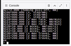
And because the long reach limit switches need a bit more pull off from the switches, you must add a few millimeters to the homing pull off as such (this is helpful if you get alarm 8):
$27=4.5 (Homing Pull-off)