Genmitsu 4030 to 6060 Expansion Guide

Introduction
In this guide, we will help you convert your Genmitsu PROVerXL 4030 CNC into a larger 6060 using this extension kit.
Tips Before Getting Started:
- You will need a large, flat area for assembly
- Your CNC machine is heavy, assemble on surfaces that will not gouge or scratch easily
- During this upgrade you will be recycling all screws. We recommend using small magnetic bowls, organizing containers or plastic bags to help keep your work area organized.
Parts List
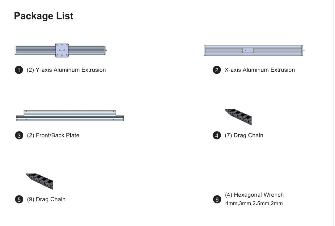
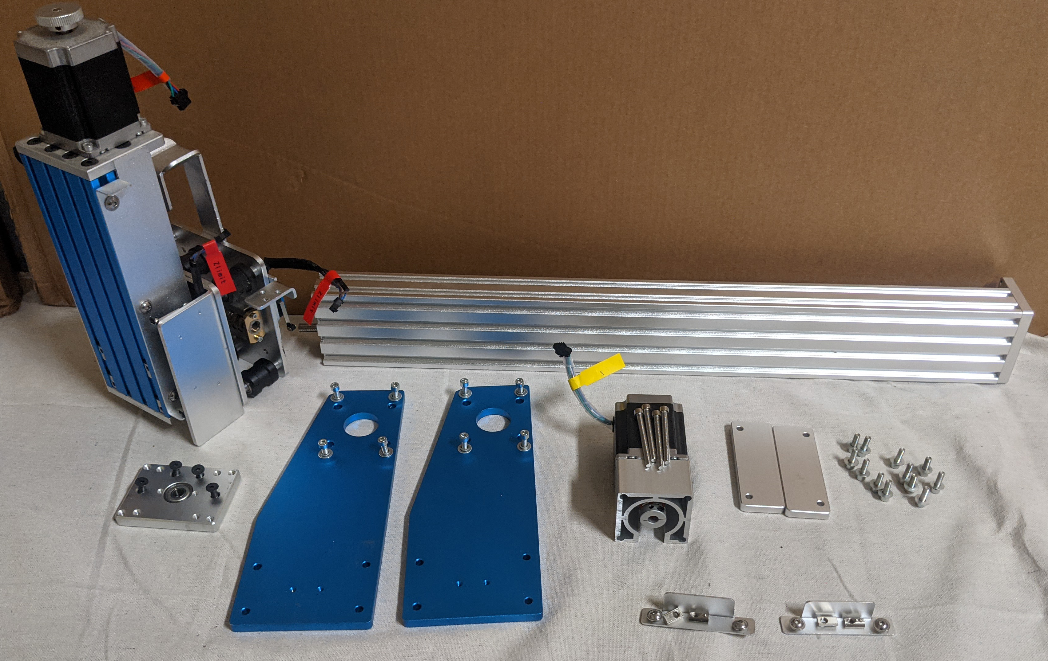
Package Contents: Ensure everything listed below has been included
Step 1: Removing & Modifying the Cable Whip
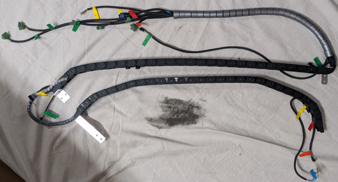
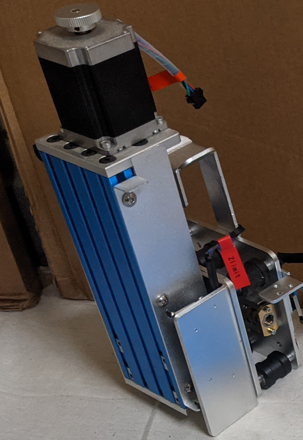
Remove PROVerXL 4030 Cable Harness/Whip. This can be performed by following the steps in your 4030XL Manual under installing your Cable Harness/Whip, only performed in reverse. If you need any guidance on this step, please see pages 20-25 of the 4030 user manual. It should look like this:
The easiest way to prepare your cable whip for the 6060 expansion kit is to break it down into its base components. Use a flat head screwdriver or something similar to open up the latches of each individual chain as shown in the image below:
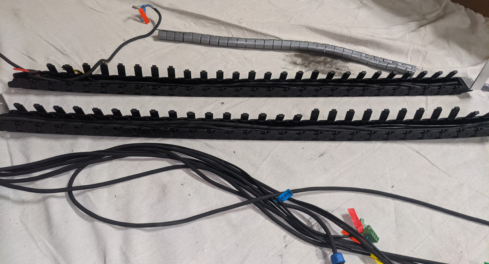
With the cable chains open, you will find that the only thing keeping you from removing all of the wiring is the pieces on each end of the cable chains, which cannot be opened up. You will need to remove these anyways in order to add the additional cable chain links that come with your 6060 expansion kit, so do so now and remove the cables:
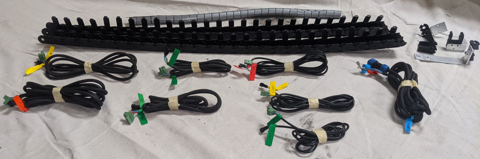
Cable Chain above is shown ready to extend. Each chain requires 27 links + the 2 end pieces. You will have a few links extra included as spares.
Reinstall the ends on your cable chains and place all of this aside in an organized fashion to be used later in the assembly process. Please note that we do not advise assembling your cable whip any further than instructed at this point.
Step 2: Working with the X-Axis Module
Disassembling the 4030 X-Axis Module
Before taking the X-Axis apart, it is best to separate it from the rest of the CNC; the easiest way to do this is to remove the 4 screws on each side of the CNC holding the gantry arms in place:
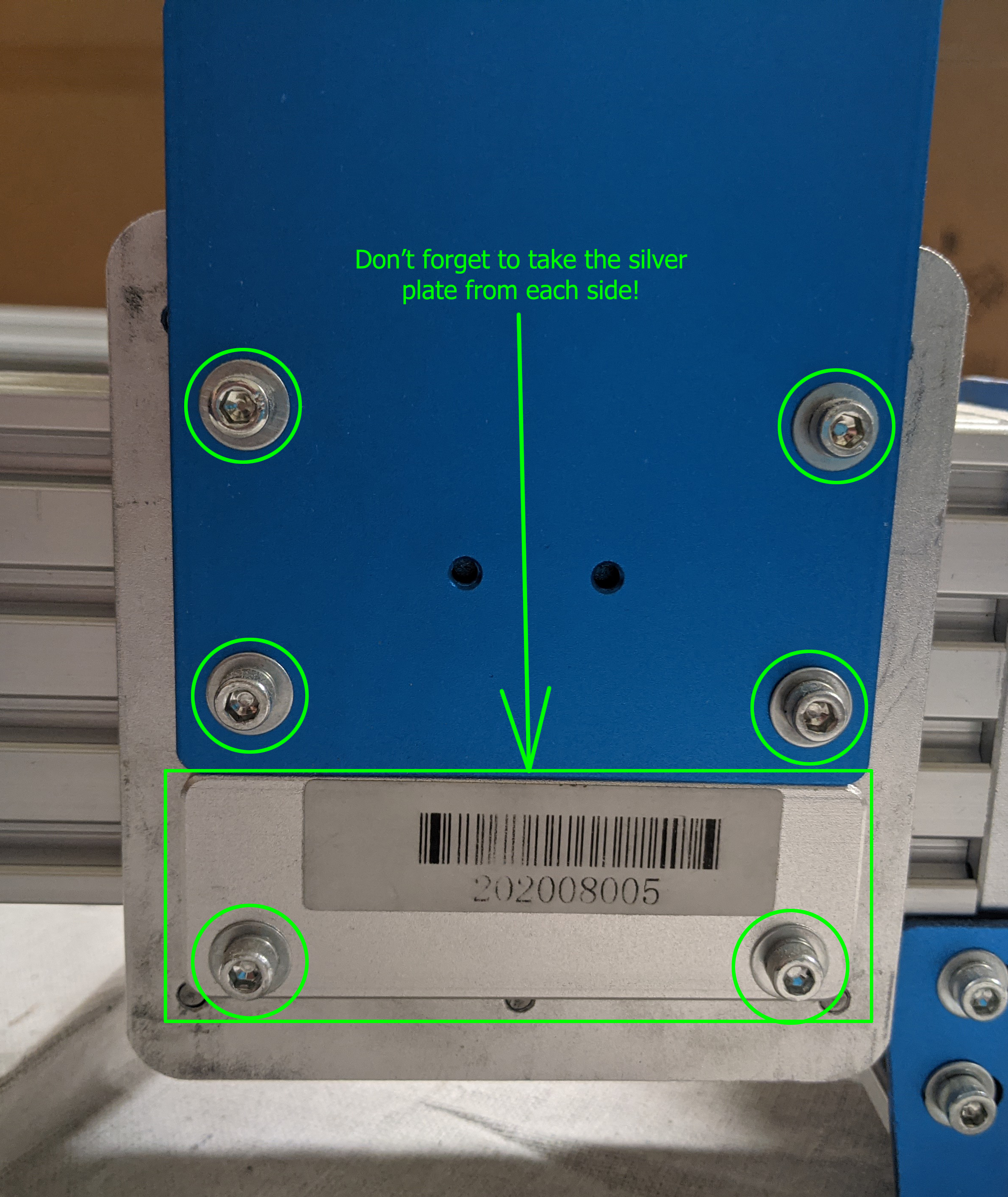
Make sure to remove the bottom silver plate as well as this will eventually need to be transferred to the new 6060 Y1 & Y2 modules. It's one of those little parts that are easy to forget so you might as well take care of it while working nearby. With the above done, feel free to set aside the base frame of your CNC to provide yourself more space to work.
From here the process of disassembling your X-Axis Module can be broken down into a step-by-step process:
1. Uninstall the X Stepper Motor, as well as the Coupler
2. Remove the blue Gantry Arms from either side of the X-Axis Module
3. Uninstall the Limit Switch Touch Plates from either side of the X-Axis Module, along with the T-Slot Nuts
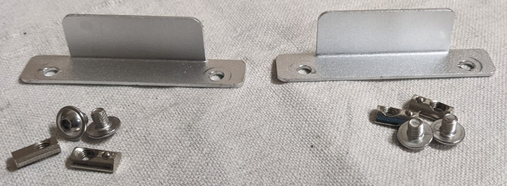
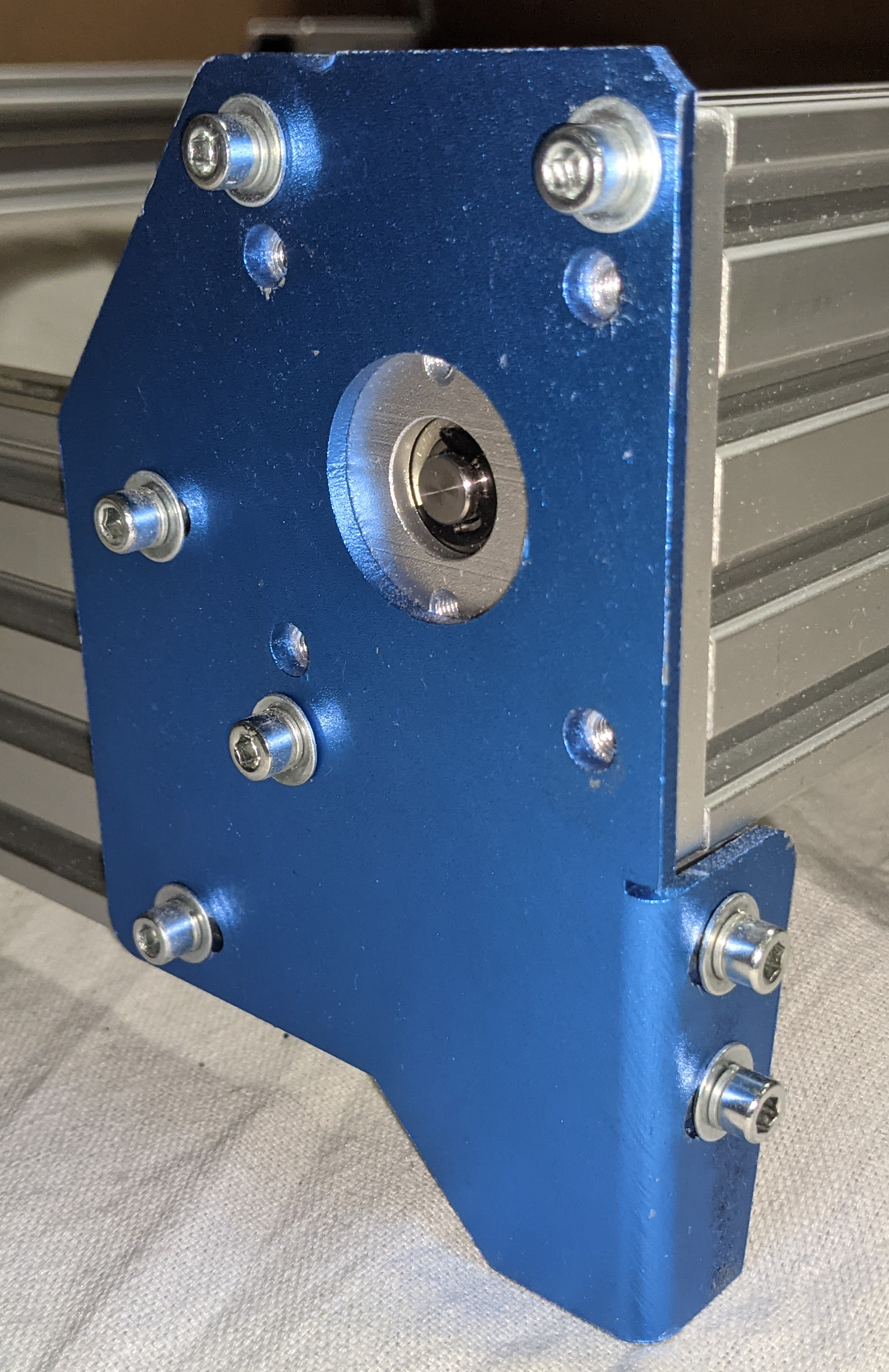
4. Remove the Gantry Side Plate from the same side that the Stepper Motor was previously connected to
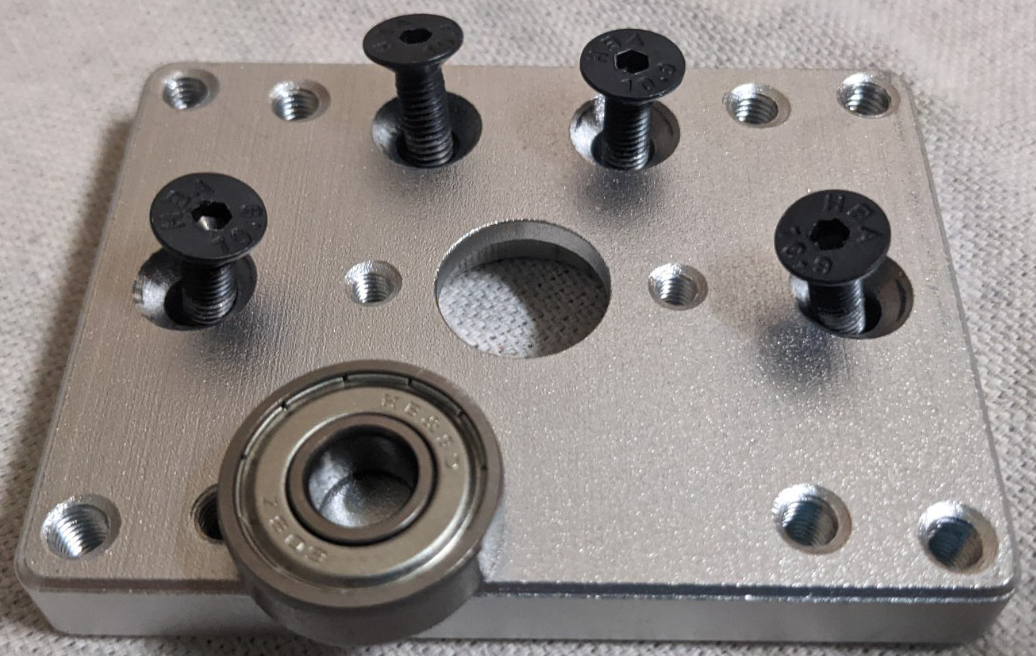
Please Note: Depending on when you purchased your 4030 CNC, there may be a substance similar to LockTite holding the above 4 black screws into place. Even if this is the case, these screws can still be removed, but it is important to uninstall them slowly but firmly to avoid any chance of damaging parts.
It is also worth noting that the ball bearing is press-fit into the plate above and is not secured by any adhesive. You may or may not need to separate the bearing from the side plate during the removal process.
5. Slide the X-Z Assembly towards the open end of the X-Axis Gantry until it comes off on its own
Assembling the 6060 X-Axis Module
1. Remove the Gantry Side Plate from your 6060 X-Axis Module on the side where the X-Axis stepper motor will be installed. The screws for this may be a different size than those that came with your 4030 , the expansion kit will include wrenches for these.
2. Slide the X-Z assembly onto the X-Axis Gantry and its lead screw. This is probably the most difficult part of the process as there are two different nuts that the X-Z assembly must be threaded into:
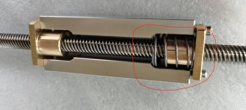
As you can see in the image above of what it looks like internally, there are two copper components that the leadscrew must be threaded to before the X-Z assembly can be fully installed into the X-Axis Gantry. One of these, the piece on the left is firmly fixed to the aluminum carriage, but the other is spring-loaded and essentially "Free-Floating" insofar that you can press in on it to compress the spring and move the copper nut.
The latter is called the "Anti-Backlash Nut" and plays a vital job in your CNC functioning properly. To thread your X-Z assembly properly you will want the Anti-Backlash nut to be ever so slightly compressed compared to its resting state, so how we suggest you do this is to thread the leadscrew through the Anti-Backlash Nut and almost but not quite to the Fixed Nut on the left-hand side. With this setup, press on the X-Z Assembly slightly to compress the spring and close the remaining gap to the Fixed nut and continue threading while applying pressure.
This process can be a little tricky and may take a few attempts, with the most common issue being that you are unable to engage the threading on the fixed nut. If this happens, try backing the leadscrew up a little, adjusting the pressure you are applying on your X-Z Assembly, and try again until you can thread it all the way past the Fixed Nut and out the other end.
3. With the X-Z Assembly fully threaded on, re-install the Gantry Side Plate from step 1
4. Install the blue gantry arms onto either side of the 6060 X-Axis Module.
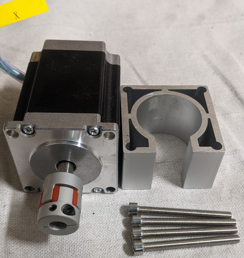
5. Install the stepper motor from your 4030 onto the 6060 X-Axis Module. Reference instructions from pages 14 & 15 of the 4030 user manual for a refresher on the process if desired.
6. Install the Limit Switch Touch Plates back on either side of your 6060 X-Axis Module, but pay attention to the note below:
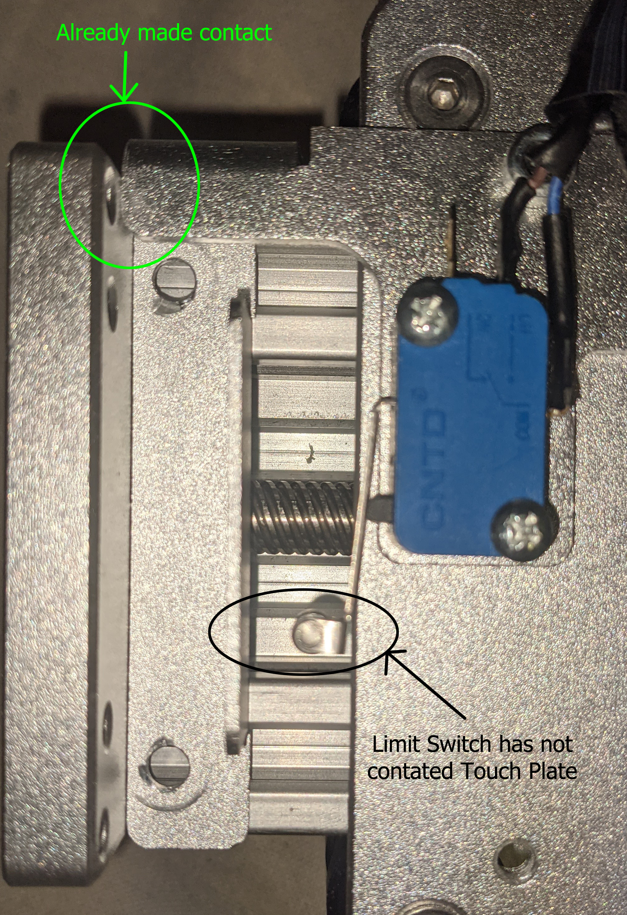
Please Note: There is a part of the X-Z assembly that sticks out for the X-Axis cable chain that sticks out quite a lot. If you install your Limit Switch Touch Plate too close to your Gantry Side plate then a collision will occur without the limit switch being triggered. It is important to make sure that the touch plate is installed far enough out to trigger the limit switch before this collision occurs.
Step 3: Working with the CNC Frame
Disassembling your 4030 CNC Frame
Because the 6060 Y1 and Y2 gantry modules come with their own carriages, the process of converting your 4030 frame to a 6060 frame is quite simple and straightforward.
1. Uninstall your Y1 and Y2 stepper motors
2. Uninstall the 4 blue pieces at each corner of the frame:
3 of the 4 corner pieces will have 7 screws and accompanying washers, while the remaining one in the rear-left corner will have 5 screws, since you had to remove 2 there to uninstall the cable whip early on.
3. Remove the touch plates from the Y1 and Y2 extrusions. Unlike the X-Axis, each Y extrusion will only have 1 of these.
Assembling your 6060 CNC Frame
Right now you should have a number of pieces sitting around:
- 2x 4030 Y-axis extrusions
- 1x 4030 Front Plate
- 1x 4030 Back Plate
- 1x 4030 X-Axis Module
At this point, you shouldn't have any need for them anymore so go ahead and put them aside after checking for any stray parts like missing T-slot nuts that you might have forgotten. With those now out of the way, grab your 6060 Front Plate, Back Plate, and Y1/Y2 extrusions.
1. Start by attaching the blue corner pieces to each side of the front and back plates.
2. Install the Y1 and Y2 extrusions into the front plate assembly, then install the back plate assembly
3. Install your Y1 and Y2 stepper motors into the CNC frame
4. Install the Limit Switch Touch Plates in the front and back of your Y1 extrusion.
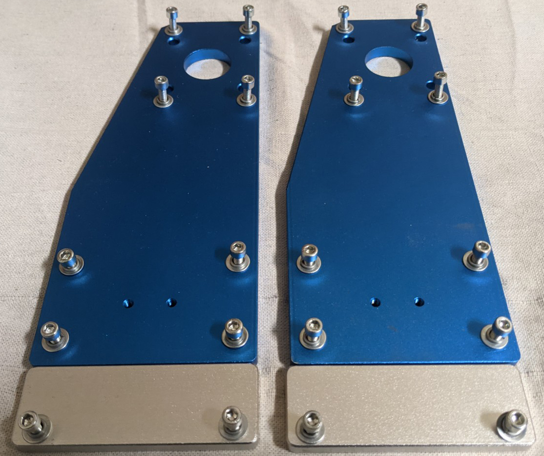
5. Install the Silver plates that you removed in Step 1 on the Y1 and Y2 carriages
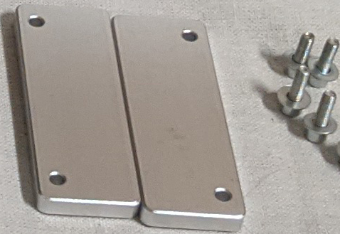
These will hold the whole X-Axis Module in place while you install the screws during installation.
Step 4: Final Assembly
At this point you should have:
- Extended X & Y drag chains
- Fully Assembled X-Axis Module
- Fully Assembled Base CNC Frame
The assembly process from this point will now mirror the way that you assembled your 4030, aside from the cable whip needing some work.
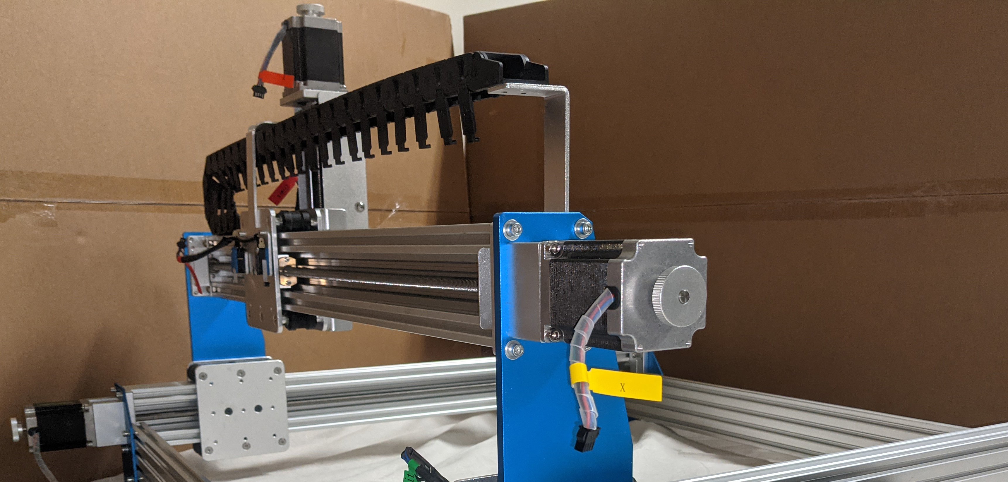
1. Install the X-Axis Module into the base frame as shown on pages 18 &19 of the 4030 User Manual.
2. Install the X-Axis cable chains into position without any wires, and make sure that all the individual links are still open from Step 1. After doing so your CNC should look like this:
3. Manually move your X-axis to the far side away from the stepper motor
4. Plug in the wires for the X Limit Switches, Z Limit Switches, Spindle, and the Z stepper motor. Bunch all of the wires together at the start of the X-Axis cable chain and slowly start the process of securing them with the latches on each chain link, starting with the furthest link and working towards the stepper motor.
5. At the end of the X-Axis chain link you will need to thread each wire individually through the final piece, which does not have a latch, starting with the Z-Axis stepper motor wire. straighten out all the wires to keep things neat and put the rest aside for the moment.
6. Plug in the wires for the X-Axis stepper motor and Y-Axis limit switch and add them to the wire bundle from the previous step. For the Y-Axis cable chain, you will find the very first link does not have a latch; You can either manually thread each wire through, but X and Z stepper motor connectors make this difficult. If you have any issues please feel free to temporarialy disconnect the first link from the rest of the Y-Axis cable chain, this will allow you to avoid threading entirely and can reassemble the chain link with the wire already through the first part.
7. Re-bundle the wires together from the other end of that first link, taking time to eliminate slack from each wire individually, and then start the process of feeding the wire bundle through each individual link, locking the latches as you go until you are through the whole chain.
8. Plug in the wires for the Y1 and Y2 stepper motor and add them to the wire bundle, and then use the wire wraps that came with your 4030 to further organize the wires.
And that's it! Your 4030 to 6060 conversion is complete! Plug everything into your control box, connect to your PC (With your offline controller disconnected entirely if you have one), power everything up and load Candle or your control software of choice and make sure that everything is in working order.
If you have any issues, such as a stepper motor not working correctly, or a limit switch not triggering an alarm state, make sure to check out all the green terminals that connect your CNC to your control box. It's possible that some connections to the green terminals were pulled loose during the process of threading the cable chain.
When in doubt, use a small flat head screwdriver to unscrew all the ports on your terminal, pull the wires out, and put them back in before tightening them back down. After doing so make sure to give each part a light tug to make sure it is firmly secured and if you are still having issues, feel free to reach out to us at support@sainsmart.com with a detailed description of what is going on, along with any relevant pictures or short videos.