Zeroing your CNC in Theory & Practice

After getting feedback from users who have purchased CNC's for the first time, we have found that that one of the most common stumbling blocks is in relation to Zeroing your X, Y & Z axis's in preparation for cutting out your project. In order to address this, this guide has been put together to help others understand the theory of why this needs to be done, as well as the practical steps to do so.
In Theory
When using 3D printers, each and every time you go to print something, the machine automatically homes so that when it starts, it is in a know position in the real world, and one that matches what the programming expects. This is possible because 3D printers are a form of additive manufacturing where stock material from outside the work area is brought within and deposited in a controlled fashion wherever the coding dictates.
On the other hand, CNC's utilize subtractive manufacturing, a method by which a piece of stock material is placed and then secured in the work area and then the CNC cuts away at that stock material until your desired shape is achieved.
This adds a layer of complication to the process because the CNC has no way of knowing where you have placed your stock material in the work area. Many CNC's don't even have the ability to home, so the question becomes how do you go about doing this?
Lets start by looking at our desired engraving:
What we can see from the above image is that this project has a start point below and to the left of the engraving. This will not be the case with every project; in fact, as you make your own you will learn to decide where you want that start point to be.
Keeping the bottom left start point in mind, now lets look at the CNC work area.
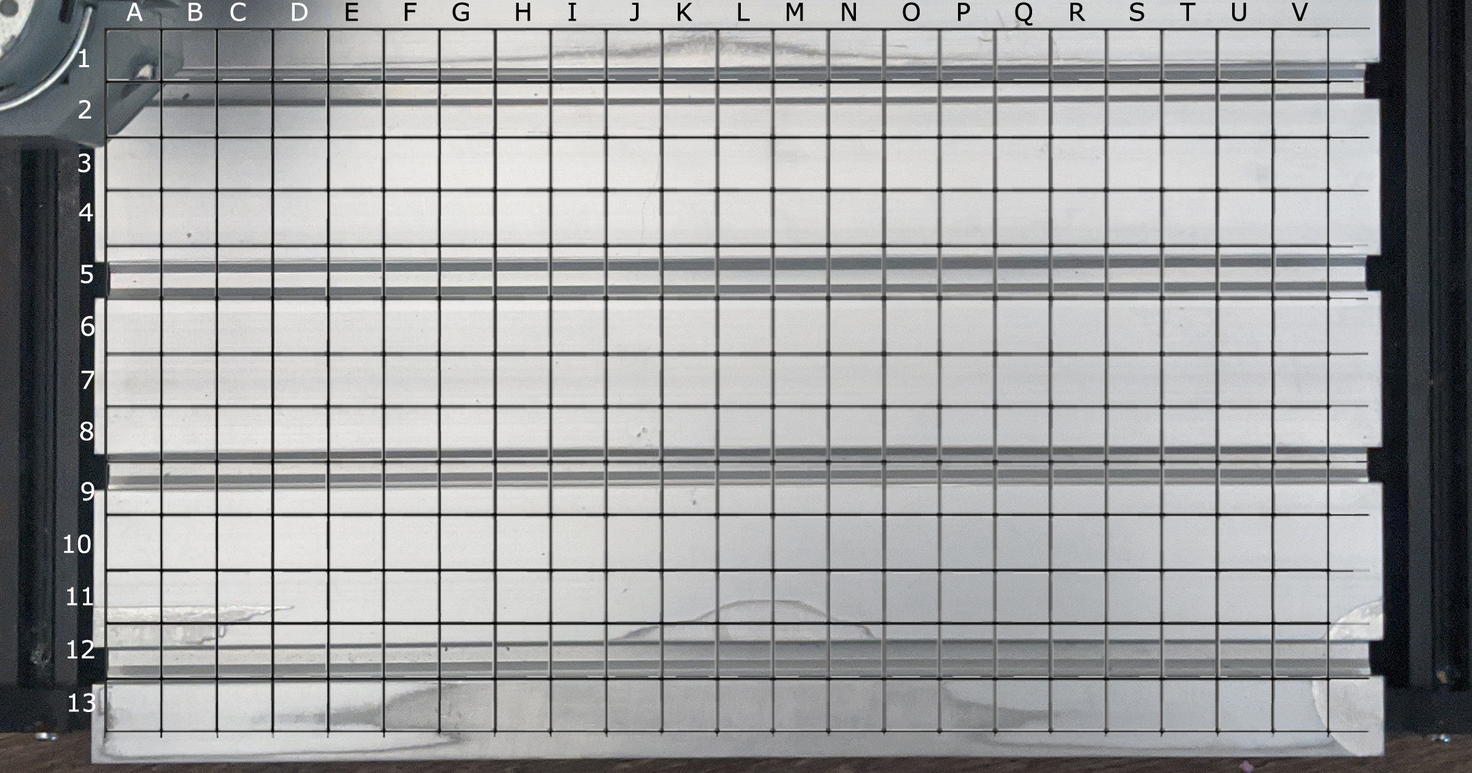
To help you understand what you are looking at, the bed of the CNC is shown from above, and a grid super-imposed on it.
If you had limit switches, this would be more or less how your CNC sees your bed after homing. If you were to start your project now, grid location A1 (directly under the spindle) would be that bottom left start point that we talked about. There is a problem, though, You cannot go any further up than A1, so the project would fail as the X and Y axis would collide with the frame.
The solution to this is to "Zero" the X, Y & Z axis, and in doing so create a new "Origin" which moves that starting point to a place of your choosing.
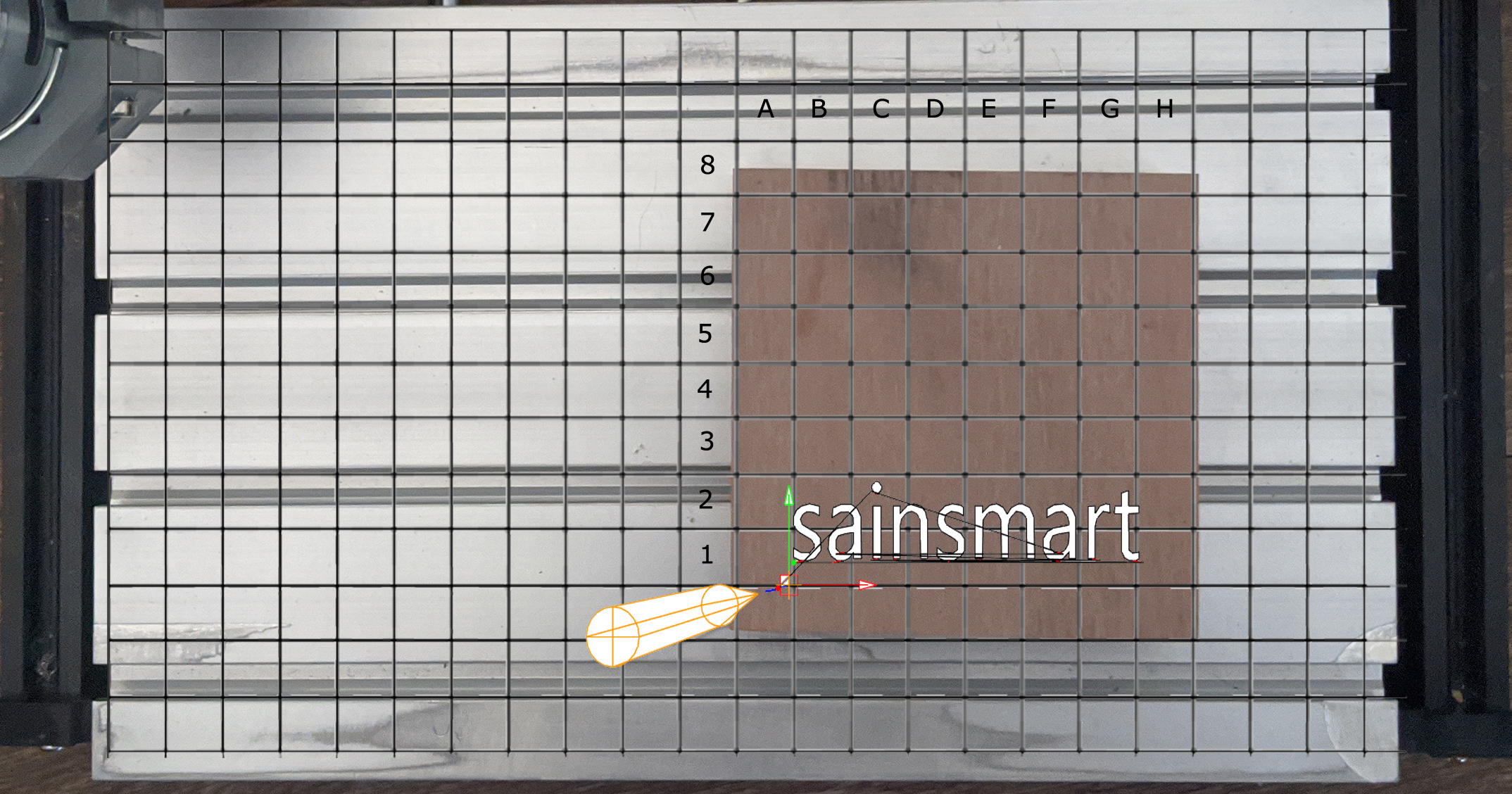
In the above image you can now see how the CNC would see things after zeroing the X, Y & Z axis. In creating this new "Origin" you are establishing the start point of a temporary new grid to frame your stock material starting at A1 and oriented in accordance to your project.
Now that we understand the theory, lets move on to putting this into practice.
In Practice
- Install & Set Up Candle: If you have not already done so, please see this guide for installing Candle CNC Controller on Windows, and this guide for Mac users.
With Candle running and your CNC powered on & connected to your computer via USB (make sure your offline controller is disconnected).
For learning purposes use the the test file, which is called "1sainsmart.nc" and should be located on the disc or USB drive that came with your CNC. If you cannot find it, you can download it from here.
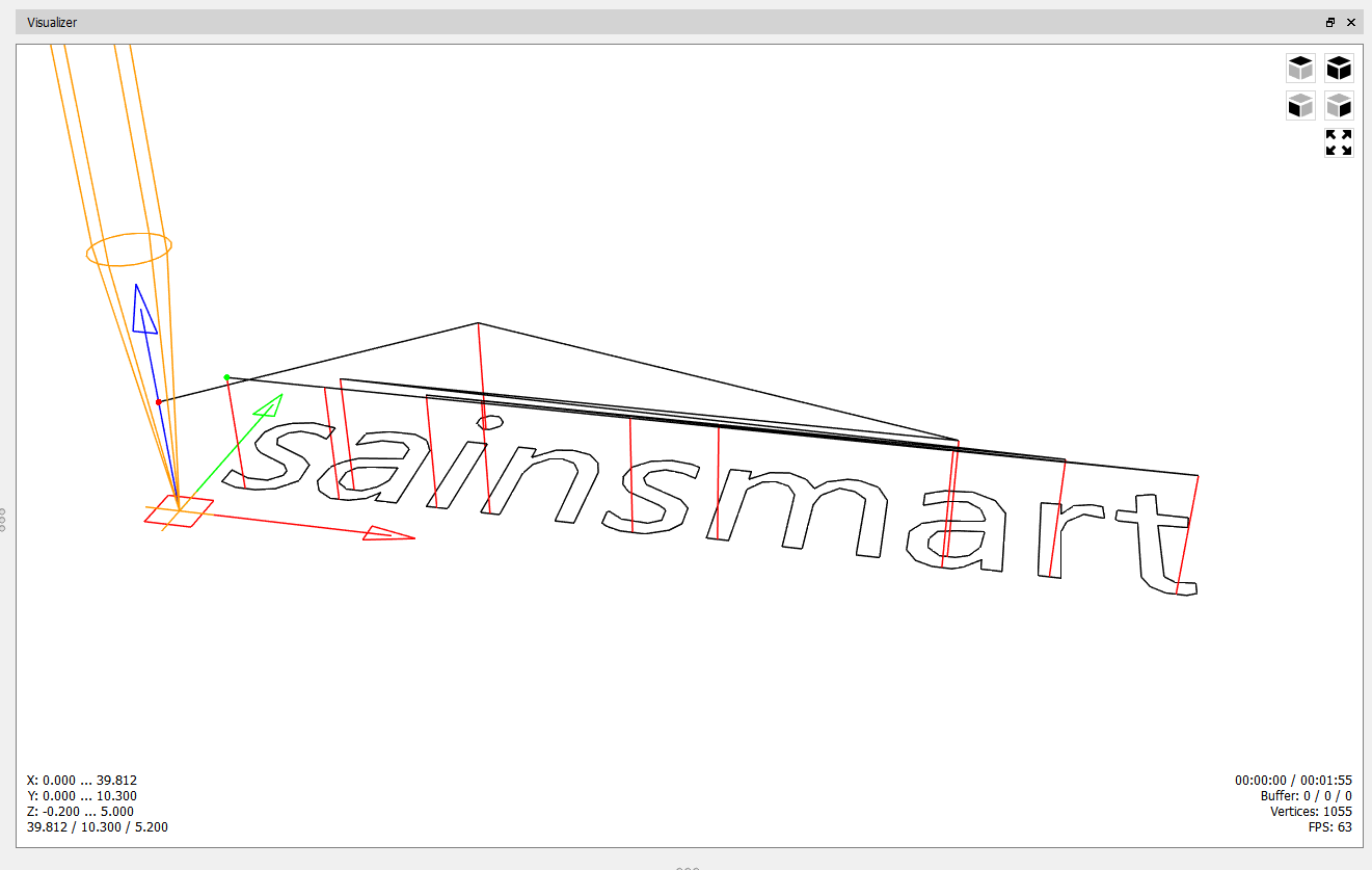
While in Candle, you will want to click File -> Open and then select the above file. After you do so, it should look something like the image below:

What you are seeing is the Visualization Window, which renders a preview of the code's Tool path that you are going to run. Because CNC's are a form of subtractive manufacturing, it is best to catch any mistakes before you start, as any mistake that gets cut will be permanent and potentially ruin your stock material.
From observing the image, you can trace the entire project in one continuous line from the Origin, to the very end. This will show how to have your CNC positioned before you start, as well as how to place clamps to avoid collisions during the engraving process.
What we need to note now Is the location of the Origin, as well as the project workspace:
Finding the Start Point/Origin:
The origin of a Toolpath is where X, Y and Z are all equal to Zero. As mentioned in the prior section, for this project, as shown visually above, the Start Point/Origin is in the bottom-left corner of the project. The location is always marked by this:
Navigating X & Y axis to your New Start Point/Origin
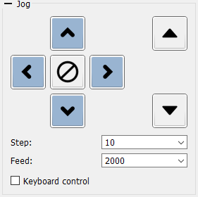
Using the Jog arrow keys above,Controls you will navigate via the X and Y axis (Ignore Z for now) to bring the tip of your engraving bit to be above your new start point/origin as best as you can and then press the  key to zero-out the X and Y Axis. You will see 2 out of 3 of the work coordinates turn to become 0 in the top right of the Candle Interface.
Note: If you are using a 3018 PROVer CNC, you will need to home your CNC before you will be able to jog any Axis.
Zeroing your Z Axis
If you do not have a Z probe:
With the end mill of your choice installed in your collet, you will need to get a piece of scrap paper, the thinner the better but not crumpled (this is important).
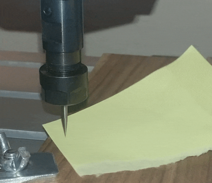
Jog the end mill down close to, but not touching the material and set your steps in the Jog menu to “.1”. Taking a small torn off bit of paper, place it between the tip of the end mill and the stock material and continually move the paper back and forth while lowering the Z axis until you feel the paper snagging against the end mill.
At this point you can say it’s good enough, or further dial in the settings by bringing steps to “.01” and continuing to raise/lower the bit until satisfied. Once it is in position, select the button to zero out the Z axis.
If you do have a Z probe:
Streamlined for ease of use, you simply set up the Z probe (See guide: What is a Z Probe & How to Use it if unsure), and place it between end mill and stock material, and press the button  .
.