Testing Your 3018-PROVer CNC

While it's easy to understand why users might want to start a project as soon as they have assembled their CNC, it is good practice when using any machine for the first time to do a final check.
Follow along with this guide in order to run your machine through it's paces and give yourself the green light to safely and easily run your first project!
Test 1: Safety Features
First and foremost, make sure that your CNC is disconnected from your offline controller, and is connected to your computer through the USB cable that came with your purchase. You need to do this because the CNC will not function properly if both are connected at the same time, regardless of whichever method you want to use.
If you don't already have Candle Installed, follow this guide for Windows with download links to do so. If you are a Mac user, you can follow this guide instead.
With your CNC initally unplugged, launch Candle and your status bar should change as shown below as you connect your CNC and unlock it:
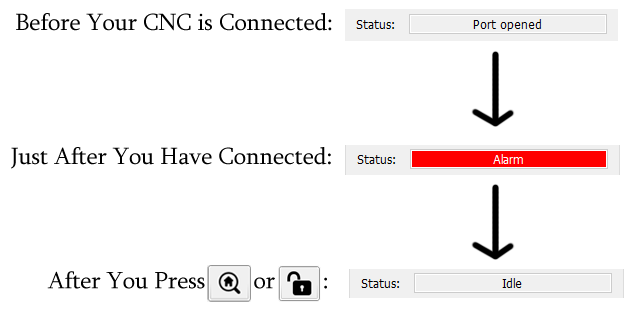
Unlike our 3018-Pro CNC, the 3018-PROVer has a feature called "Homing" enabled which, while useful, has your machine start up in an "Alarm" state until such a time that you home it.
Usually you would home first thing after connecting to your CNC, but in this case, what we want to do is test the alarm state, which should protect yourself and your CNC under any number of unexpected circumstances.
Having not Homed, nor selected Unlock, try moving your CNC around using the Jog arrows:
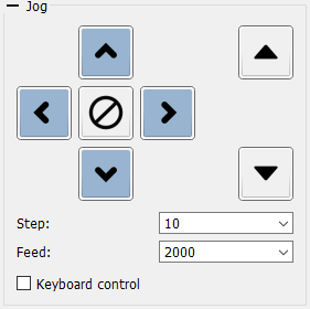
Under the Alarm state, you should not be able to move your CNC at all until such a time that you either Home or Unlock. If this is the case then you are good to go!
Test 2: Do All Axes Move in the Correct Direction?
The X, Y and Z axis all have a Positive (+) and Negative (-) direction. While these directions should be oriented correctly at the time of purchase, it is best to test this anyways. In the image below you will see what orientation each jog button should control, as well as what direction your CNC should move in based on that button:
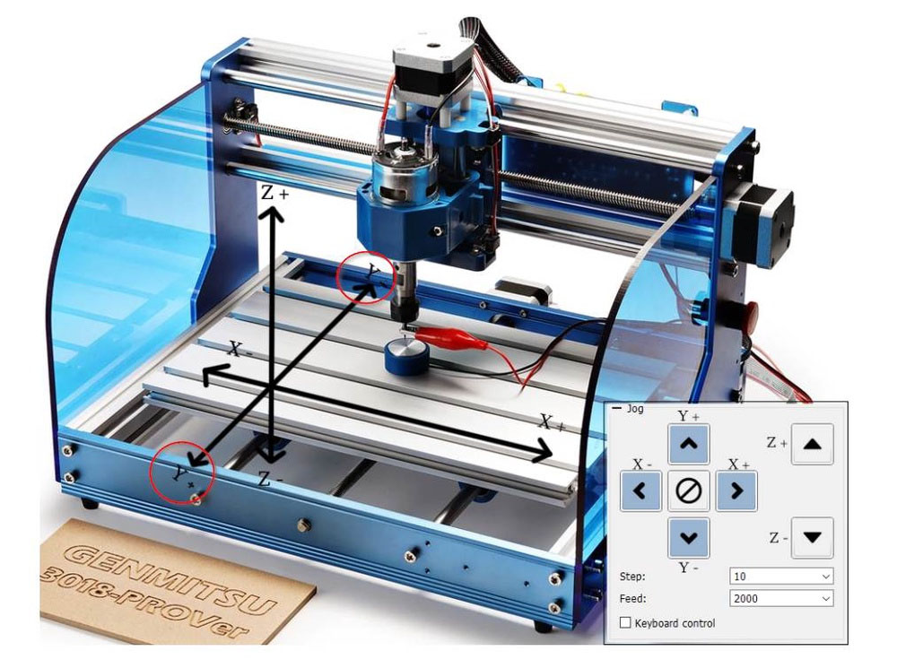
In order to test this, within Candle set the Jog Step to 10. Make sure the spindle is not close to the edges of the router and is in the middle of the Z movement, if necessary with the power OFF turn the threaded rods by hand to move the spindle. With that done, follow through with these tests:
- Hit the right jog button (X+), the X axis should move 10mm to the right, X- sends it to the left.
- Hit the Up jog button (Y+), the Y axis should move 10 mm towards the front of the bed, Y- sends it back.
- Hit the Z+ (right up arrow of the jog buttons) and the spindle should move away from the bed by 10mm, Z- sends it down.
Please note that while the X and Z axes are straightforward, the Y axis can be confusing as the bed itself is what moves, and not the spindle.
Test 3: Homing & Limit Switches
Testing Limit switches
Each axis on your CNC has a (+) and (-) switch that is meant to be triggered if your CNC ever tries to move beyond the limit that it is mechanically able to, triggering an Alarm state whenever this occurs outside of Homing.That is how it should work, but it is important to test for parts that might have been damaged during shipping, and that you have Hard Limits enabled in your firmware.
In order to test this, move each axis into the center roughly, although it's fine as long as no limit switches are pressed before starting. With the CNC in place, use your finger to press each of the six limit switches installed into your CNC.
Each time you press a limit switch a blue light will glow from the limit switch itself and the Console will show; Alarm: 1 [MSG: Reset to continue]. Note that the Status panel on Candle remains as "idle". Before attempting to test another limit switch go to Candle/Device and click on Reset {symbol}. Then click on Unlock {symbol}.
Test each switch this way. If the limit switch does not light up, or the Console read Alarm:1, you may have a problem and should reach out to technical support at support@sainsmart.com
Testing Homing Cycle
Assuming that your limit switches all tested fine, it's time to move on to test your CNC's Homing Cycle. As mentioned before, when you connect your 3018-PROVer to your computer, it will automatically start out in the Alarm state. The correct way to get past this is by Homing or pressing the button with the house on it.
When the button is pressed, you should see the following in order:
- The Z axis should next move towards the (+) Z axis, triggering the limit switch and then moving off, before triggering the same limit switch again much more slowly for the sake of accuracy. If homing in the +Z direction fails to activate the limit switch, check the position of the spindle motor. If it's mounted too high, it will hit the edge of the Z stepper motor and prevent contact with the limit switch. The fix is to lower the spindle motor slightly.
- As this happens, the X and Y axis should start moving at the same time:
- The X axis should move towards the (-) X axis until it triggers the limit switch, and then moves off before triggering the same limit switch again, only much more slowly for the sake of accuracy.
- The Y axis should move towards the (+) Y axis until it triggers the limit switch, and then moves off before triggering the same limit switch again, only much more slowly for the sake of accuracy.
Once everything has stopped moving, you will be in the default Home Position, and your X, Y & Z will likely be some combination of negative numbers.
If this was not the case, for example, your CNC started by trying to home the X or Y axis first, or the homing direction is wrong, then your stepper motors might be plugged into the wrong location, or there might be issues with your firmware. Should there be any issues, please feel free to contact us at support@sainsmart.com.
Test 4: Wire Management
In the excitement of getting your CNC assembled, it can be easy to remember small details like wire management, but this is important to ensure the proper operation of your machine. loose wires can get caught while your machine is moving around, resulting in failed projects or damaged components if you are unlucky.
Provided with your CNC are a number of cable holders, a wire sleeve and a sealer strip which the instructions show you how to strategically place, which keeps every wire out of harm's way. Even so, once you set this up, the X and z wires might still be long enough to cause some trouble.
To test this, use the jog command to move the Z axis down in the (-) direction until it is close to, but not touching the limit switch. If you trigger it by accident, you'll need to manually move the Z axis up a bit and then reset the CNC. Do the same with the X axis next. moving it close to, but not touching the (-) limit switch.
Both these points are just before the maximum amount your wires should ever have to extend. Check to see how much slack each wire has at this point. If there's too much, try to tuck it away as best as you can, but make sure there is enough wire so that each axis is able to trigger it's limit switches.
With the cables at their optimum length, test each axis separately, moving back and forth between the maximum (-) and (+) while watching to see if the wires catch on anything. Assuming there are no obstructions, you're good to go!
Test 5: Spindle Motor
Before testing the spindle motor, make sure the collet/collar is properly tightened and that your hands and other limbs are far away from the spindle.
While connected to candle in an Idle state, go to the Spindle section, which looks like this:
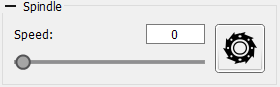
The button to the right of the speed slider can be used to manually turn the CNC spindle on and off. With the slider set at 0, turn the spindle on and slowly drag the slider to the right until it is at it's maximum speed.
As you bring the slider to the left, you should hear the spindle getting louder and lounder. Since you are not cutting anything during this test, the sound should be strong and consistent at any level, not fluctuating unless you raise or lower the speed yourself. Should you see the spindle cut out or stutter, your spindle may be damaged and you should reach out to us at support@sainsmart.com for further help.
Test 6: Emergency Stop Button
To test the Emergency Stop Button, start the Spindle motor as you did at the last test, and then then hit the Emergency stop button.
When the button is pressed, the spindle should stop, and the motherboard will have effectively been turned off and is now totally unresponsive to any commands from Candle until the Emergency stop button is released.
To release the Emergency Stop Button, turn the button itself clock-wise (to the right) and once it does not turn any further, lightly pull the button out and let go. Once this is done, Candle should now show an Alarm state, the router has just been turned on/connected.
If the button did not work, you should trace the wire back to the motherboard and make sure that it is plugged in all the way, and plugged into the right location.
Test 7: Z-Probe
Please see this dedicated article related to the Z probe to learn how to set up and operate your Z probe.
Test 1-7 Troubleshooting
Issue | Solution |
Candle can communicate with the router but nothing moves. | Ensure the On/Off switch on the motherboard is ON. Verify the 24V external power supply is connected correctly. |
Router is totally unresponsive to Candle | The Emergency Stop Button may be pressed, or the Emergency Stop Button is not connected that the Jumper is not set to the ON position on the motherboard, or the jumper is in place in the motherboard socket. |
An Axis does not move | The Stepper motor may be connected to the wrong location, or a wire may be loose. |
The wrong Axis moves | The Stepper motors might be connected to the wrong ports |
Limit switch does not work | Check that the limit switch wire is firmly connected at each end |
Spindle motor does not turn | Check that your wires are fully connected at each end. |
Spindle motor turns but the LED does not light up | Make sure that thee Red wire is connected to M+ on the spindle motor and the Black wire to the M-. |
Limit switch LED stays on | Manually move the related axis so that the spindle moves away from the LED until it turns off. |
Z-Probe fails | Make sure that the bit you are using is conductive, clean of debris and firmly connected via the alligator clip. Make sure the Z-Probe is connected to the motherboard correctly. |
After Zeroing Z via the probe, the tip of the bit is not perfectly flush with the stock surface when Z = 0 | This means that your code the CNC for the Z probe is inaccurate. To work properly, the CNC needs to know the exact height of the Z probe. Use a caliper to measure the probe height and adjust accordingly |
Candle shows a Serial port error message in the Console window | Make Sure:
|
Test 8: Run a Test Engraving
Assuming everything is fine, or fixed based off of tests 1-7, lets go ahead and do a test engraving next. Follow the steps and images below in order to proceed:
- Load the sample G-Code file sainsmart.nc (File/Open) from the Micro SD card or CD that came with your CNC.
- Run a homing cycle.
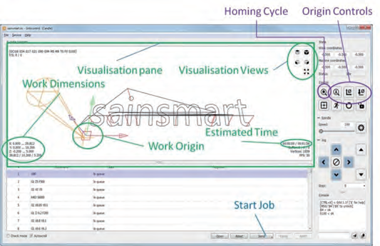
- Examine the Work Origin and Work Dimensions in the Visualization Pane; the Work Origin is wherever you set the XYZ axes positions.
- The Work Dimensions tell you how far to the left … right etc. each axis will move during the job. In this case the Work Origin is at the bottom left, at the top of the stock and the X axis will cut 0 to the left and 39.812mm to the right of the origin, the Y axis will cut 0 to the front and 10.3mm to the back. The Z axis will move down by 0.2mm and up by 5mm (Note: the Z axis down movement is normally the depth of cut, the 5mm is the distance it will move above the stock when positioning the bit).
- Fit one of the supplied engraving bits into the spindle and tighten the tool holder using the spanners (wrenches) provided with your CNC, making sure it is mounted so the tip can reach the full depth you are trying to cut. ( In this case at least 0.2mm below the top of the stock)
- To tighten the collar/collet to the spindle, you use one spanner/wrench to keep the spindle from turning freely and the other to turn the collar/collet while the spindle is held still.
- Select a piece of wood of that is at least the full side of your test engraving, so approximately (~40mm x ~11mm x~1mm) is the area that is engraved, but this must be clear of any clamps to that are being used to hold the wood still. The last thing you want is for the spindle to hit the clamps, so be sure they are 100% clear of the entire tool path.
- Mount the wood onto the bed securely using the Work Clamps, it should have a flat base and surface, the cut will only be 0.2mm deep so if it’s not flat the cut will be of an uneven depth.
- Using jog commands position the bit on the XY axes to where you want the job to start and using the Origin Control button (shown below) to Zero the X and Y axis:

- Place the Z-Probe base underneath the bit, connect the alligator clip to the bit and hit the Z-Probe button which looks like this:

- Remove the Z-Probe base and the alligator clamp and set them aside.
- Hit Send (at the bottom of the window) to start the job. The Elapsed time and an estimate of the total time needed is given in the Estimated Time in the Visualization Pane. Once your CNC is done, you should have something like the image below:

Engraving Troubleshooting
Hopefully everything works as expected, but if not:
Issue | Solution |
Nothing at all is cut or the cut is too deep. | This means that your code the CNC for the Z probe is inaccurate. To work properly, the CNC needs to know the exact height of the Z probe. Use a caliper to measure the probe height and adjust accordingly |
A limit switch was activated during the job | Make sure that, for this test engraving, that your X and Y axis are zeroed in the intended bottom-left corner (So that it will cut above, and to the right of that point. |
The depth of cut is uneven, only parts are cut. | Make sure that your bed is level and that your stock is as well, |