Genmitsu 3018 CNC Quick-Start Guide

Introduction
Intended for new users of CNC's in general, this guide will walk you through using it for the first time. In order to ensure that you are prepared for this process, please make sure that you have done the following:
- Assembled your CNC: This will not be covered here, please see the user manuals for the 3018 Pro (Here) & the 3018 PROVer (Here)
- Installed & Set Up Candle: This guide will assume that this step has already been taken care of. Please see this guide for Windows users, and this guide for Mac users
Step 1: Working with Candle
With Candle running and your CNC powered on & connected to your computer via USB (make sure your offline controller is disconnected).
For this first test run, you will need the test file, which is called "1sainsmart.nc" and should be located on the disc or USB drive that came with your CNC. If you cannot find it, you can download it from here.
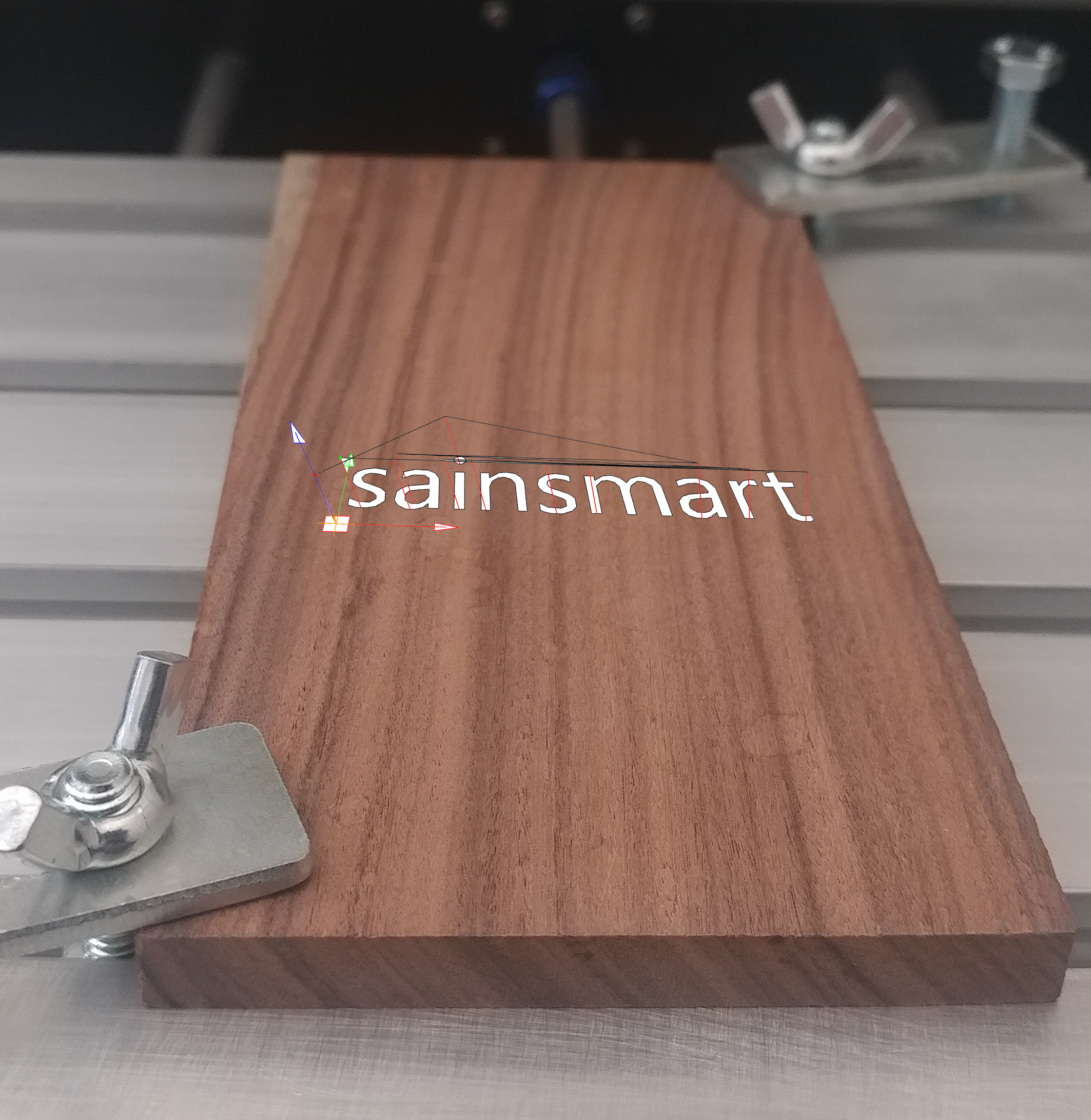
While in Candle, you will want to click File -> Open and then select the above file. After you do so, it should look something like the image below:
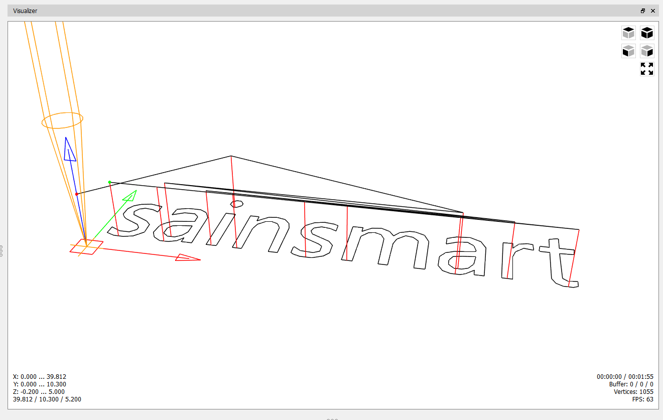
What you are seeing is the Visualization Window, which renders a preview of the code's Tool path that you are going to run. Because CNC's are a form of subtractive manufacturing, it is best to catch any mistakes before you start, as any mistake that gets cut will be permanent and potentially ruin your stock material.
From observing the image, you can trace the entire project in one continuous line from the Origin, to the very end. This will show how to have your CNC positioned before you start, as well as how to place clamps to avoid collisions during the engraving process.
What we need to note now Is the location of the Origin, as well as the project workspace:
Finding the Work Coordinate Origin:
The origin of a Toolpath is where X, Y and Z are all equal to Zero. Depending on the project, the location of the origin can vary, but the most common locations are the center of your project, or (in this case) the bottom-left corner of your workspace. You can locate the origin by looking for where this image is seen:

Finding your Project Workspace:
The project workspace is essentially an imaginary box, which represents the maximum area that your CNC will be working with. To find this, you look to the bottom-left corner of the visualizer, where you will see the image below. This measurement, shown as Length x Width x Height, will be used to determine where to place clamps, as well what stock material the project will fit on.
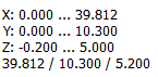
It is always smart to give yourself a little extra room for error and safety, so while the workspace dimensions are 39.812 mm x 10.3 mm x 5.2 mm, lets assume it is 40.5 mm x 11 mm x 5.5 mm
With the information gathered for later, and the toolpath inspected for any potential issues, it is time to move on to the next step.
Step 2: Stock Material Selection & Workholding
Stock Material Selection
We now know that the project workspace is 40.5 mm x 11 mm x 5.5 mm, and that this represents the area where the text will be engraved. In order to select a suitable piece of stock mater, you need to consider the following:
- Is my stock material wide and long enough enough for me to fit the full engraving?
- Is my stock material thick enough for my project needs?
- Is my stock material also thin enough that the Z axis can move at least [Insert Z Workspace Value] up and away from the stock surface?
- It is worth noting that the Z value of the workspace, does not imply that your CNC will be cutting that deeply. This value also includes space for vertical movements and retractions.
- Is there room on the stock material, well outside of my workspace, to place clamps that can hold the project down?
For a successful project, the answer to all of these questions needs to be "Yes," and for the case of this demonstration, a 60 mm x 120 mm x 6.5 mm piece of Pau Ferro wood is being used. Of course, lots of shapes and sizes can be used just don't use anything too thick or too thin.
Workholding:
Along with your CNC, you received supplies for 4 plate clamps which, when assembled, look like this:
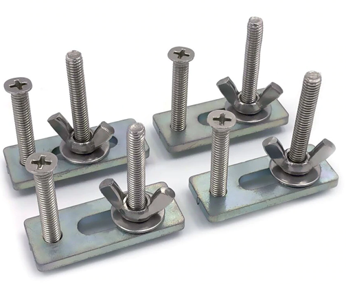
In the below demonstration, you can see how to use them to firmly secure your stock material to the CNC bed.
Throughout your CNC bed, there are a number of strategically places slots which are T shaped, allowing the bolt head facing downwards to slide in.
With the wing nut loose, you want to slide the clamp aiming for a top corner, well away from where you plan your workspace to be. Once the metal lip makes contact with the wood, you can tighten the wing nut down to press it against the stock material.
With pressure applied, you can tighten the additional screw or bolt in order to really lock it down, although take care to not tighten things too much. The clamp is made of steel and the bed is made of aluminium, so you might accidentally damage the bed or its T slots.
Rinse & Repeat with additional clamps. While only two clamps are shown being used above, using all four clamps is always the best choice to make sure the wood is fully secure.
Make sure as you secure your stock to the bed, that it is not crooked, and is in fact square to the machine to the best of your abilities.
Installing your Engraving Bit
To install your engraving bit, you will need the following:
- 1x ER11 Collet
- 2x ER11 Spanners (Wrenches)
- 1x Engraving Bit (Careful, very sharp)
- 1x Spindle
- 1x Spindle Cap
Below is a visual demonstration of the installation process:
To follow along, do so in order:
- Take the ER11 Collet and the black spindle cap. You will want to push the collet, wide side facing downwards, into the cap until you hear an audible click. Visually inspect the collet to make sure that it is fully seated in the spindle cap before continuing. It will be very loose and wobbly even after being properly seated, so don't worry about that.
- With the ER11 Collet installed, thread the spindle cap onto the spindle, but do not tighten. You just want it threaded enough that it will not fall off on its own.
- Insert the end mill into the ER11 Collet with the pointy side facing downwards. You will need to hold on to the bit (careful not to injure yourself) and use your other hand to manually tighten the collet until it can hold the bit on its own. Continue to tighten by hand as much as you are able.
- Please note that the collet should only be touching the full cylindrical shaft portion of the bit. No flat or cutting edges should be inside of the collet. Failure to do so could lead to a damaged bit, failed project or worse.
- It is also important to consider how much of your bit is exposed. If your bit is not long enough for deeper cuts into other projects, your spindle will collide with your stock material.
- Each of the two spanners/wrenches are of different sizes. One is meant to hold the spindle in place to keep it from turning, while the other is meant to tighten the spindle cap. With a wrench/spanner in each hand, firmly tighten the spindle cap while preventing the spindle from turning.
Selecting your Work Coordinate Origin
The next step after this is actually navigating to, and zeroing out your axis with your CNC on the Origin, but before we get to that, you need to determine where you want to place it. This selection will be entirely arbitrary for the most part, with considerations to what you want the end results to be. The only hard requirement is that you make sure it is well clear of any clamps, such as how it was selected below:
Navigating X & Y axis to your Work Coordinate Origin
With your CNC fully prepared, it is time to go back to Candle now.
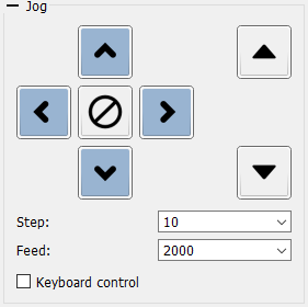
Using the Jog Controls, shown above, you will want to navigate the X and Y axis (Ignore Z for now) to bring the tip of your engraving bit to your desired Word Coordinate Origin as best as you can and then press the  key to zero-out the X and Y Axis. You will see 2 out of 3 of the work coordinates turn to become 0.
Note: If you are using a 3018 PROVer CNC, you will need to home your CNC before you will be able to jog any Axis.
Zeroing your Z axis
Now you need to zero-out the Z axis in order to have your work coordinates completely set. There are two ways to do this:
If you have the 3018 Pro or another CNC that does not have a Z-Probe
As shown above, you will need a piece of scrap paper, the thinner the better but not crumpled (this is important). Bring the end mill close to, but not touching the material and set your steps in the Jog menu to “.1”. Taking a small torn off bit of paper, place it between the end mill and the stock material and use one hand to continually move the paper back and forth, while using the other hand to lower the Z axis until you feel the paper snagging against the end mill. At this point you can say it’s good enough, or further dial in the settings by bringing steps to “.01” and continuing to raise/lower the bit until satisfied. Once it is in position, select the button to zero out the Z axis.
If you have the PROver or have modified your 3018 Pro to allow for a Z-probe
Streamlined for ease of use, you simply set up the Z probe (See guide: What is a Z Probe & How to Use it if unsure), and place it between end mill and stock material, and press the button  .
.
Start the Project!
You are now ready to go! Make sure to wear all relevant personal protection equipment and select "Send" for the CNC to start.
Please note that it is important to stay with your CNC at all times while running as a safety precaution. Should anything go wrong, the project can be aborted or paused via Candle or an emergency stop button in the case of the 3018 PROVer.